CNC Milling
For this week, the challenge is to make an intern box using the CNC Machine!
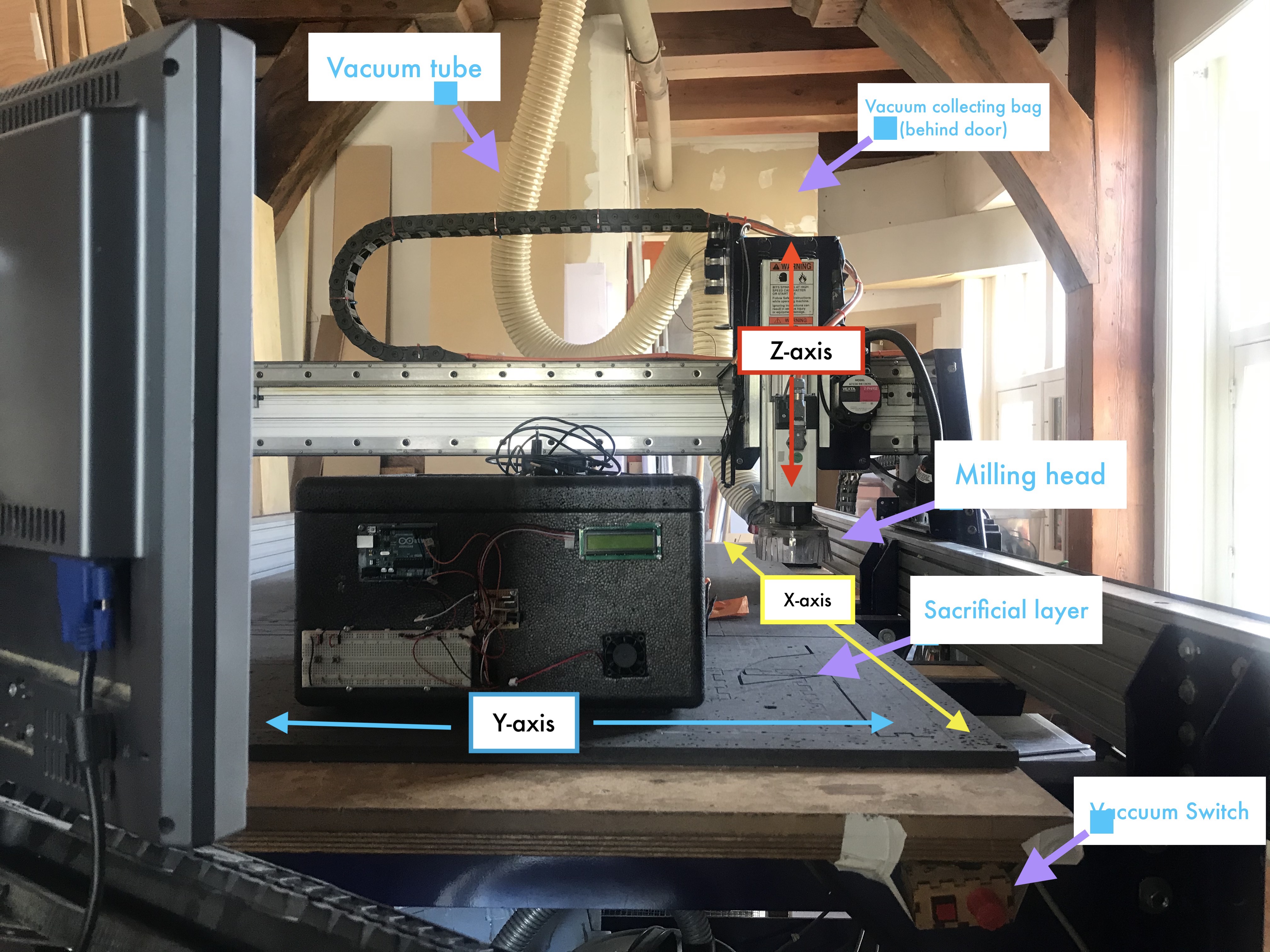 The shopBot Mill
Safety Instructions
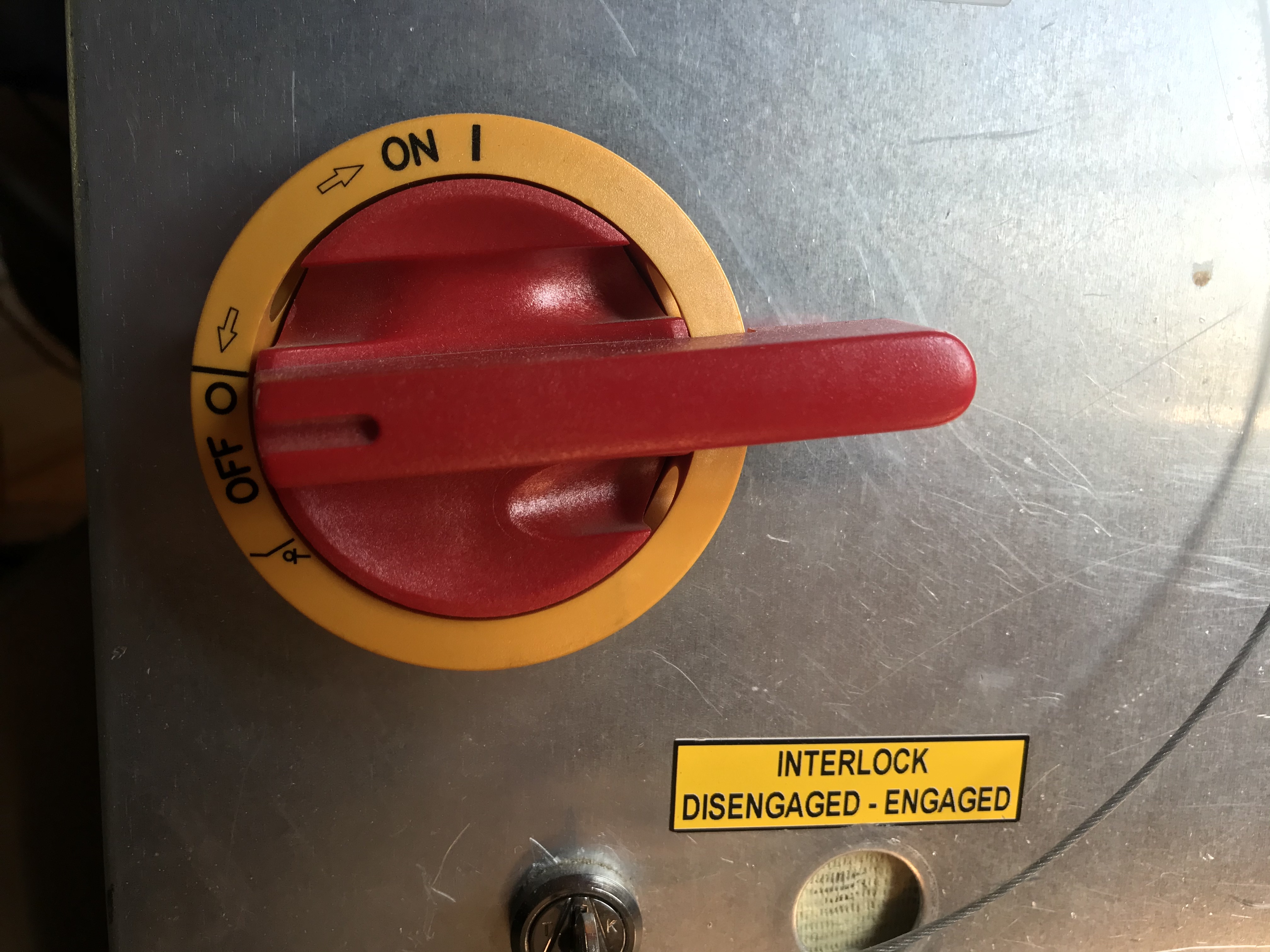
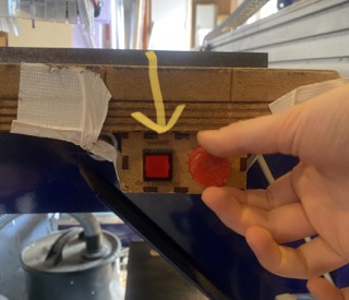
- There is an emergency stop button which is located at the front of the machine at the bottom(big red & yellow). Once pressed, then stop the vacuum by pressed the button at the upper corner.
This button is only to be used in cases of real emergency since once pressed, the machine will need to be rebooted.
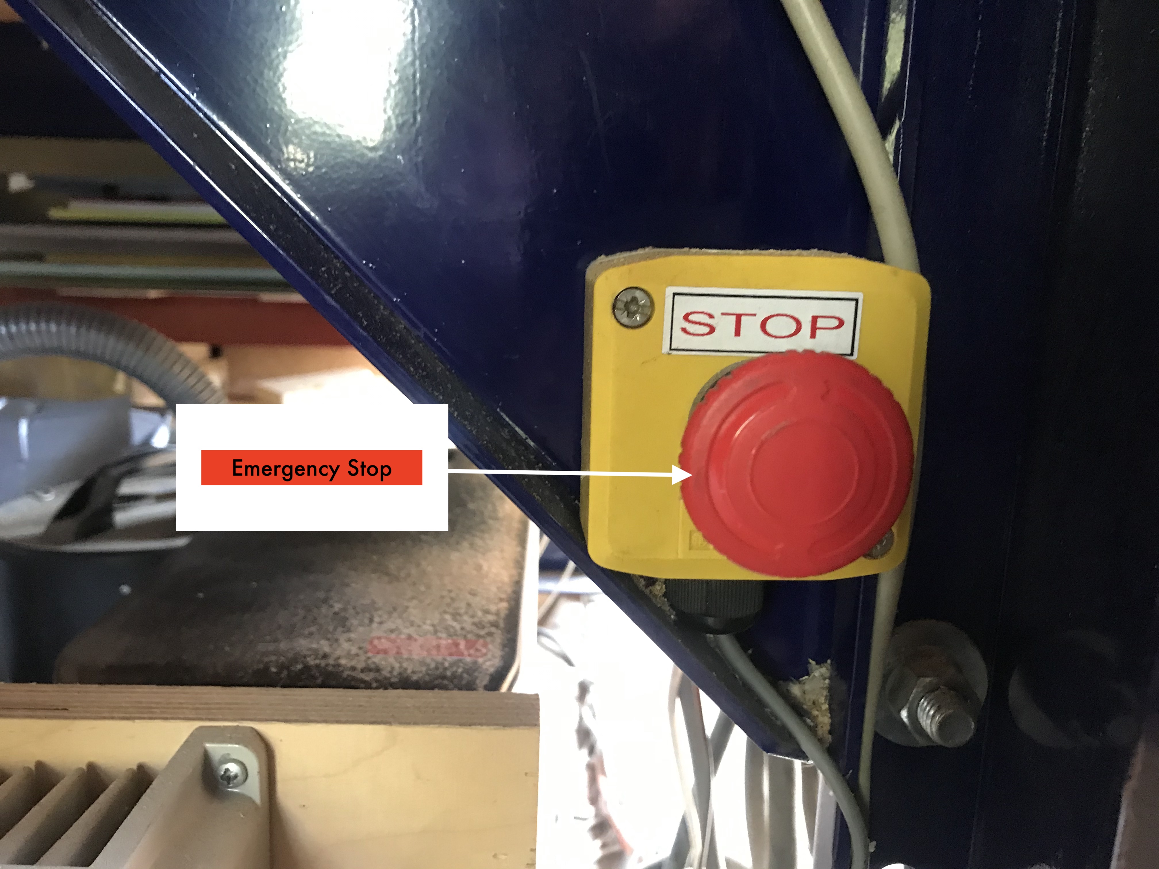 The emergency stop (bottom-right) and vacuum on/off button (top-left)
- There is an emergency exit door
- There is a fire extinguisher in the room
Personal Safety
- Make sure your hair is tied up. If your hair is long put in in bun.
- Take off accessories
- Be mindful not to wear loose clothing that could get hooked to the machine
- Wear Safety Googles
- Use ear protection
- Stay away from the machine while it’s operating
Fire Safety
- At the back of the room, there is a vacuum that sucks the chips that the mill creates.
- Metal screws are used to fix the wood to the sacrificial layer.
- The biggest risk of creating a fire is when the milling bit comes into contact with metal. This creates sparks that are then sucked into the vacuum bag.
- To avoid such risks, add drilling holes to your design. The machine will mark the drilling holes on a first toolpath pass.
-
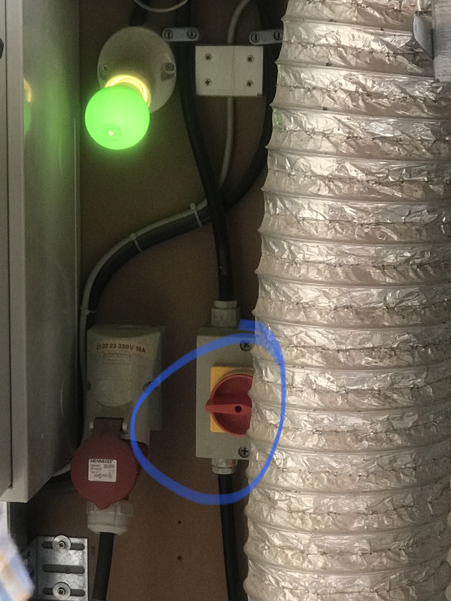
Incase of fire, turn off the electronics panel located at the back of the room
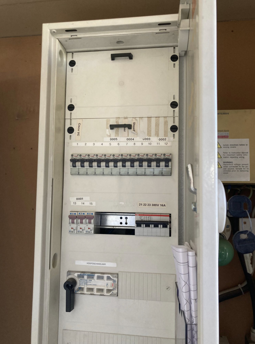 Electronics panel
If you hear or see that the bit is hitting the screw, do the following :
- Stop the machine with the emergency stop button at the front of the machine.
- Stop the vacuum with the button at the front of the machine.
- Go to the room with the dust collector bag, loosen the round metal clip with which the plastic bag is attached to the machine.
-
Inspect the bag.
- If a little smoke is coming out:
- Close the bag to reduce the flow of oxygen.
- Walk out of the building and inspect again.
- If a lot of smoke is coming out / a fire has started:
- Close the bag to reduce the flow of oxygen and see if that stops it enough to then walk out of the building (possibly through the emergency exit at the back of the milling room).
- If it’s really bad, throw it out of the window (do call down to warn people).
Other Safety
- While shopBot is running, maximum number of people in the room should be 2 at a time.
- Make sure the bed is clean, no clutter or other items are on it.
- Make sure that nothing is touching the machine from the sides Clear the space, by organizing the wooden pieces away so there’s spacing.
![]() Make sure there is no wooden pieces or other objects touching the machine from the sides
Make sure there is no wooden pieces or other objects touching the machine from the sides
- Make sure the spindle is not going to bump into any screws.
Preparing the file in VCarve Pro
VCarve is one of the most impressive and efficient toolpath options. Depth is determined by the tool angle and width of vectors
- Turn on computer, take out any attached USBs just in case.
- You can edit your design on a software called v carve pro
- Open VCarve Pro & Create a new file
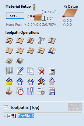
Setting up the material
-
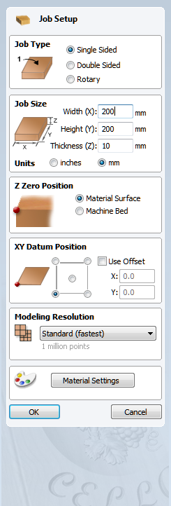
Job size (X & Y) : Measure the height and width of your material and assign them to Width(x),Height(y), or use the measurements of your overall design as long as it fits on one board or break it down as you see is suitable. Knowing that the material you will be using either matches or exceeds the size of the finished product
-
Material (Z) : Set Zero at the bottom if you intend to cut the piece all the way throughthe material, otherwise you can adjust it according to what you intend to do. Also note that if you are using wax, foam or for 3D mole making, put the Zero near the top!
-
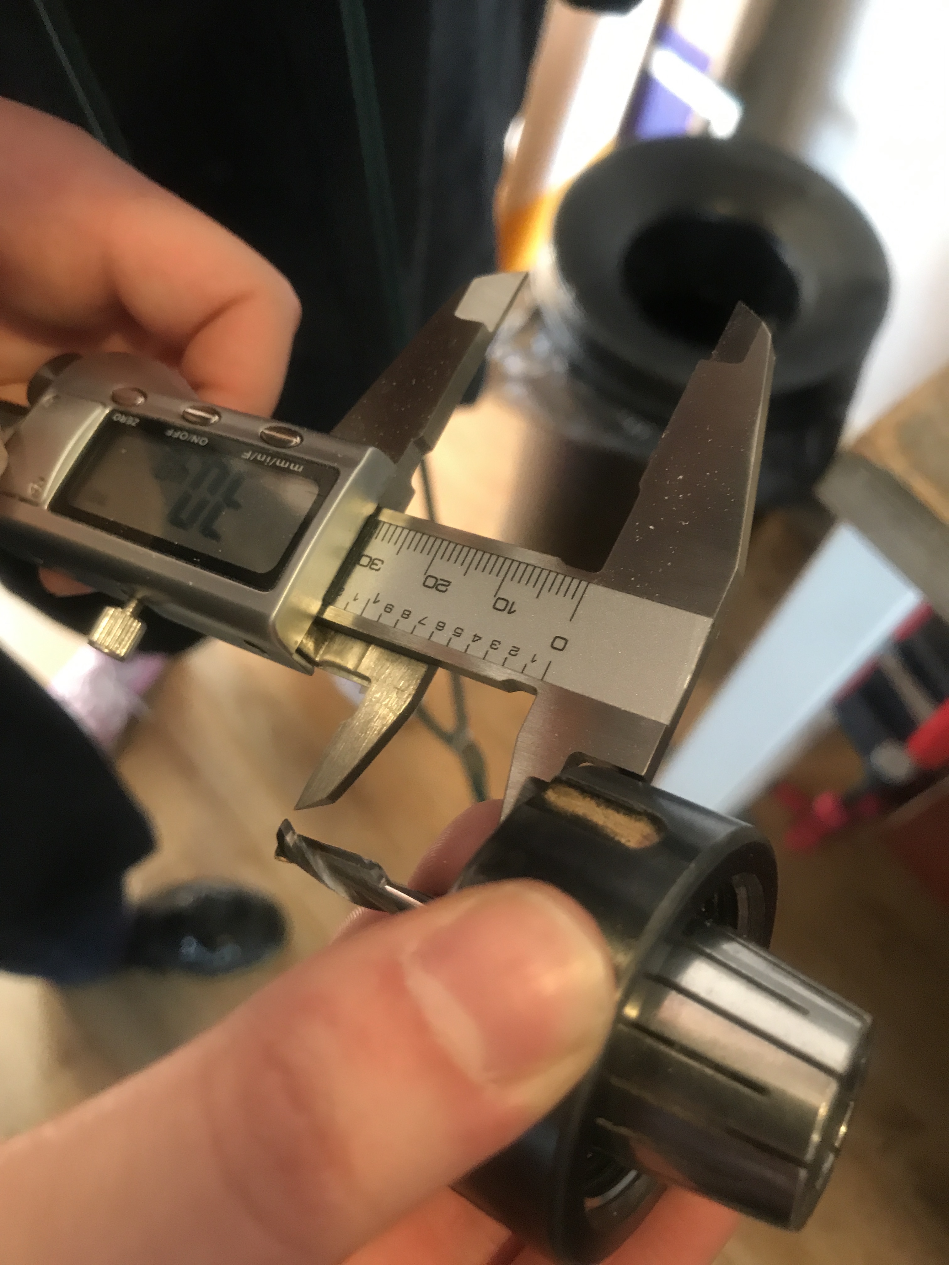
Measure the thickness of your material by using a caliper.
-
XY Datum position : Use the bottom left corner(See the picture below)
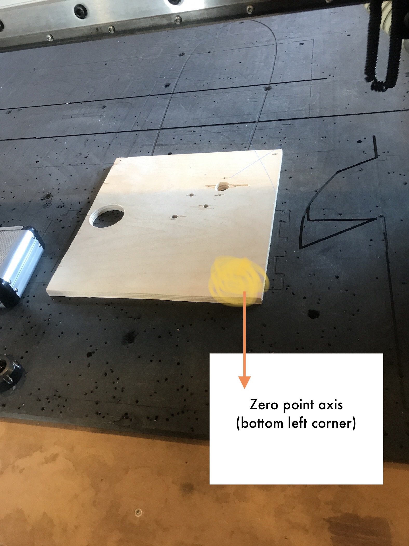 Check that there are no screws or anything on your material
- Units: Use mm
-
Set modeling resolution to high & appearance to pine, just for the sake of visualisation within the software, yet not so important to do so!
- Then import your file by going to File > Import > Vectors, choose your file and press ok
File Operations
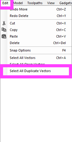
- First, make sure that there are no duplicated vectors. You can do that by going to edit > select all duplicate vectors > delete. This is important so that the software does not get confused about which area we are asking it to recarve. If you do have a design that requires overlapping, you can create a seperate vcarving toolpaths which will run in the order you require to achieve the effect you desire.
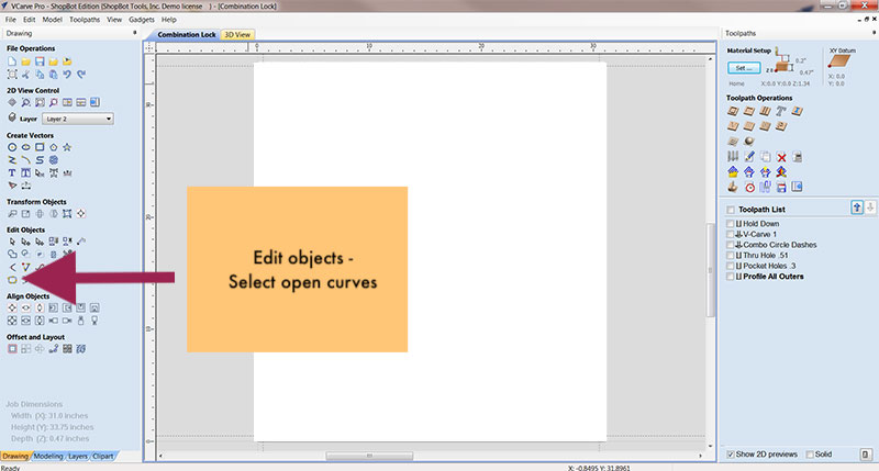
- Go to edit objects > Join open vectors (with tolerance)
- Use transform object to move or rotate object
![]() Align to selection and We aligned it to the center
Align to selection and We aligned it to the center
Changing Milling Bits
Types of milling bit There are a few things to consider when changing the milling bit. Types of milling bit differ in diameter and type. For instance, there are end mills as well as flat heads & ball heads.
-
Diameter : Thickness of the mill. The thicker the mill, the faster and less precise it is. The thinner, the slower but more precise. The standard diameter is 5mm.
-
Flutes : The number of threads of the mill. The more flutes, the more precise the milling, yet the slower it is.
- One flute: For rough/prototype work, Fast, but not very neat.
- Two flutes : Standard, more precise.
The flutes are important for the speed of the machine, because the mill needs to drain the material. The more flutes, the more difficult to drain the material.
5 mm two flutes, end mill
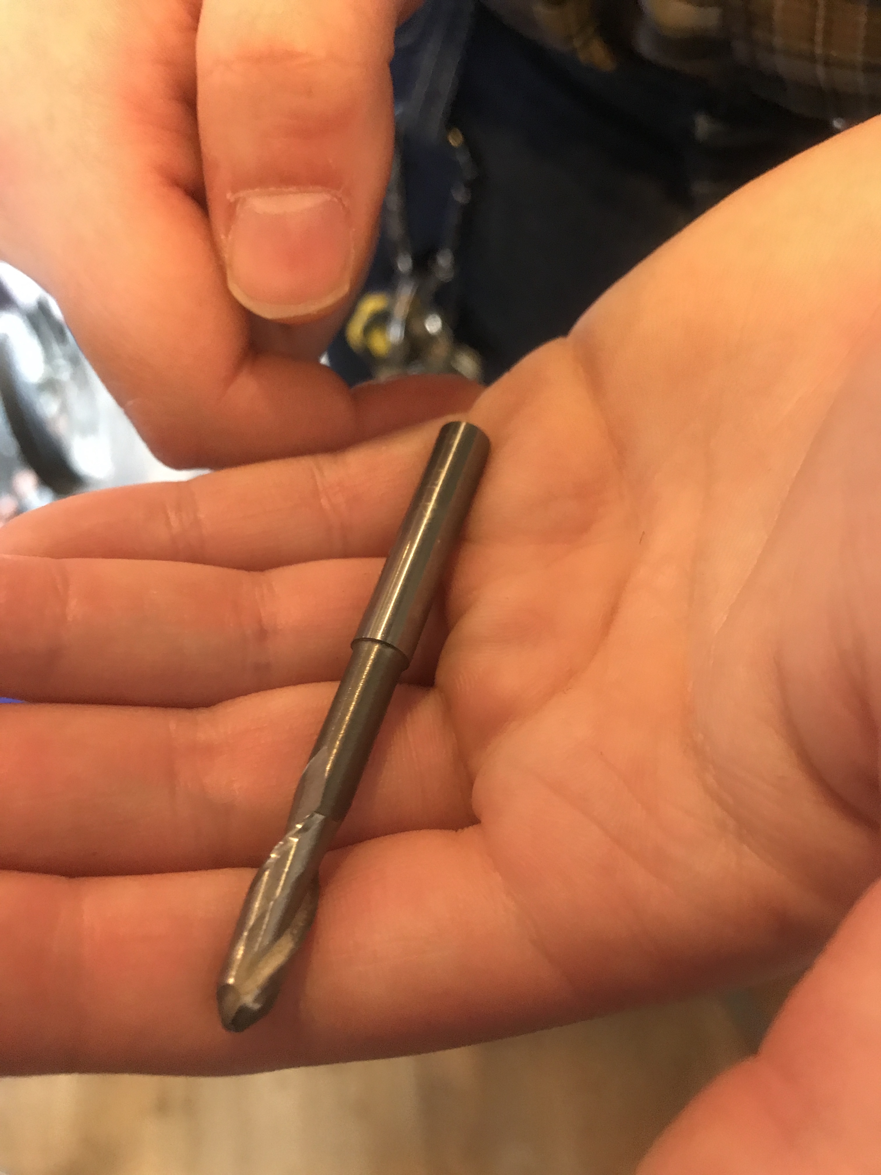
6 mm two flutes, bull nose which means it’s rounded
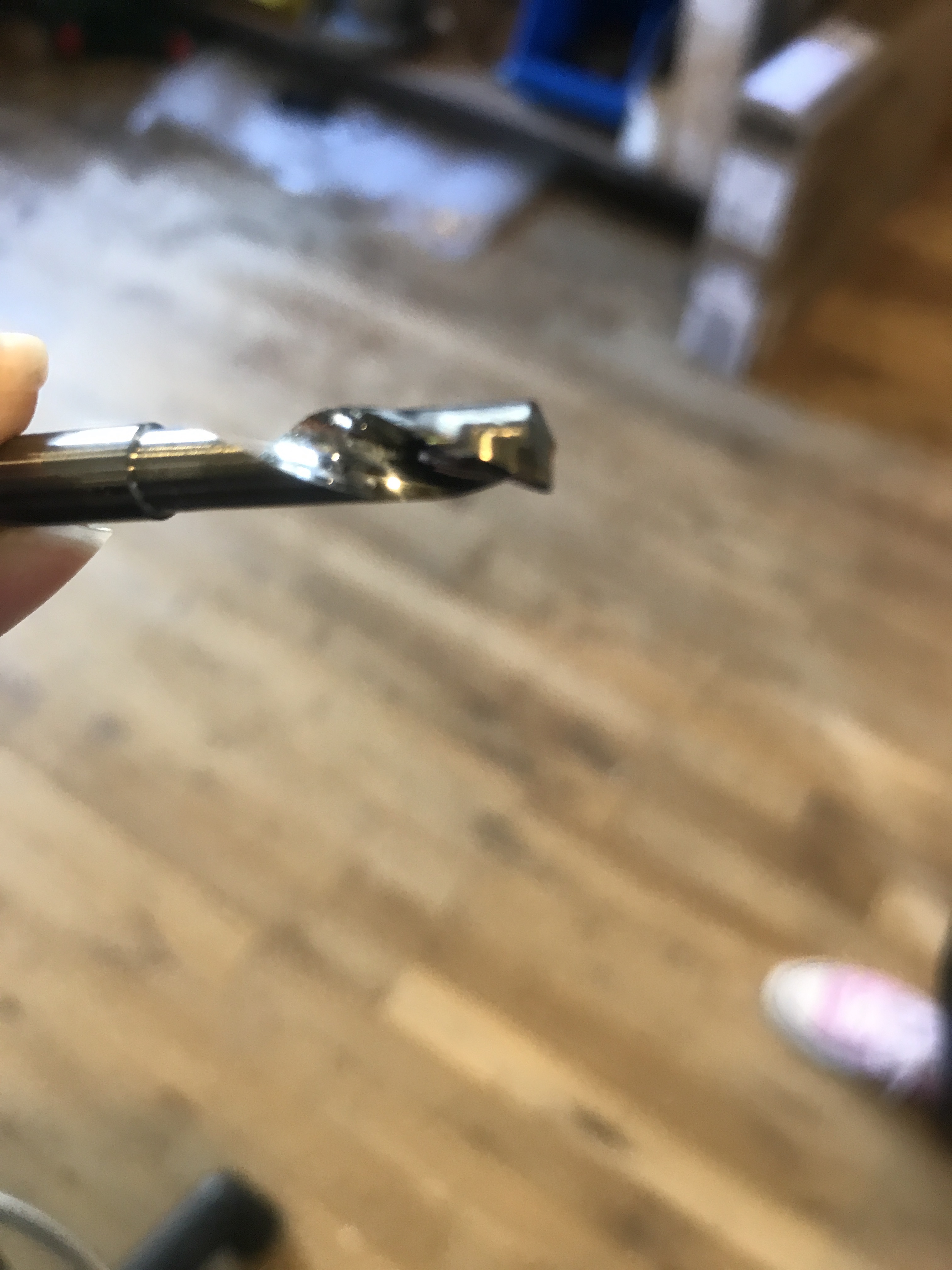
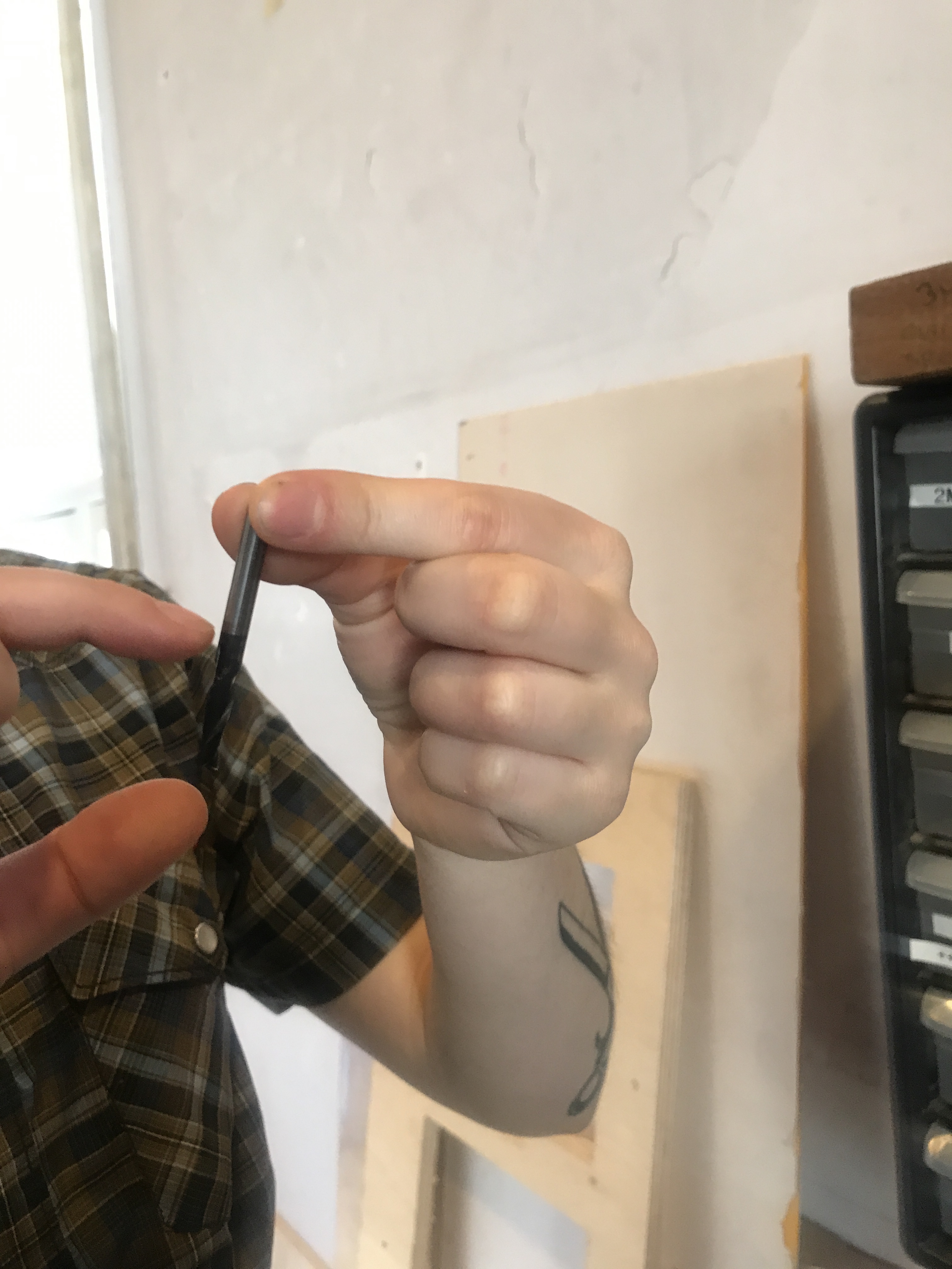
One flute, one edge
The nut, the collet and the millig bit
- First, push the nut out of the collet
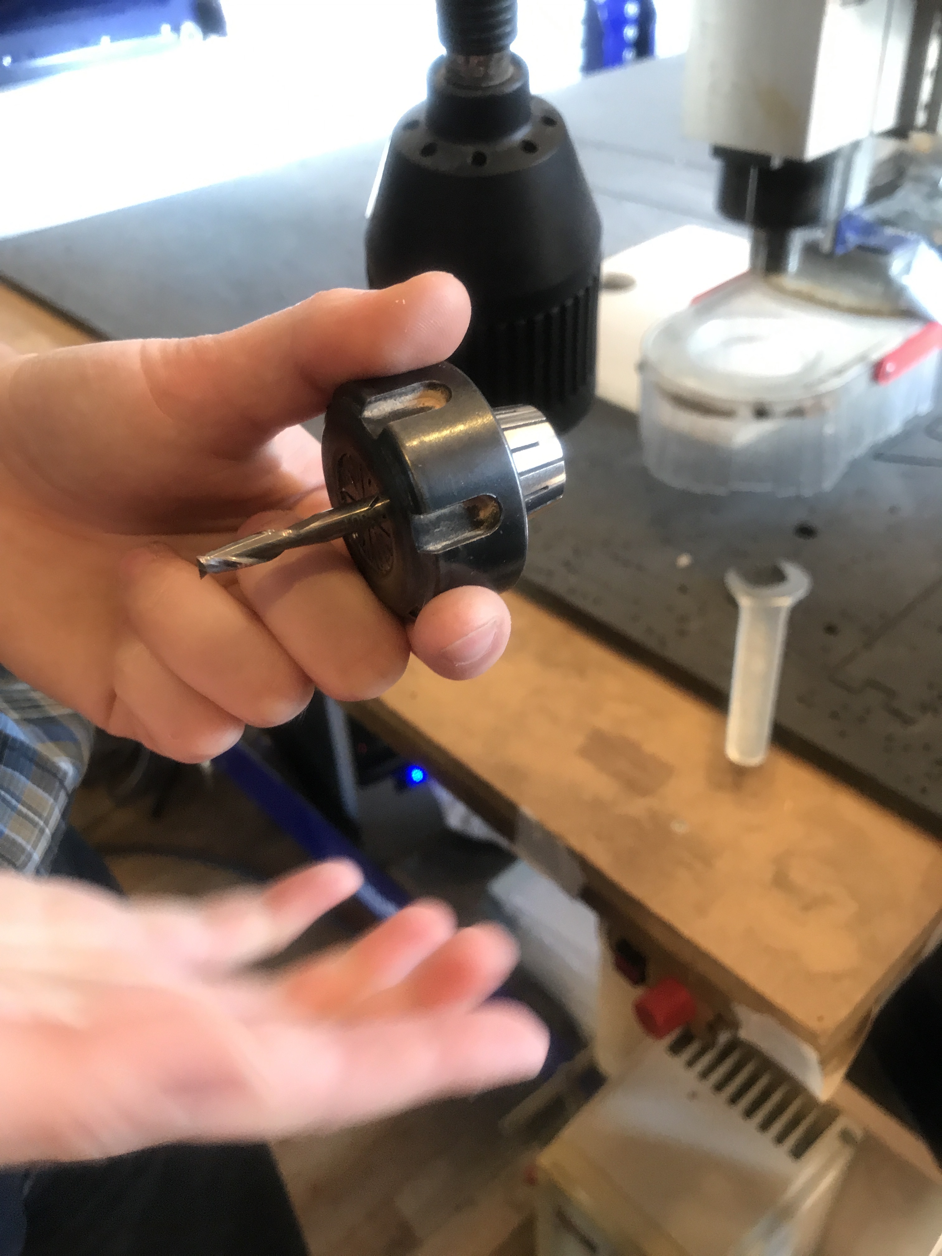 We have to push it out
-
Then clean it up, make sure there’s no dust
-
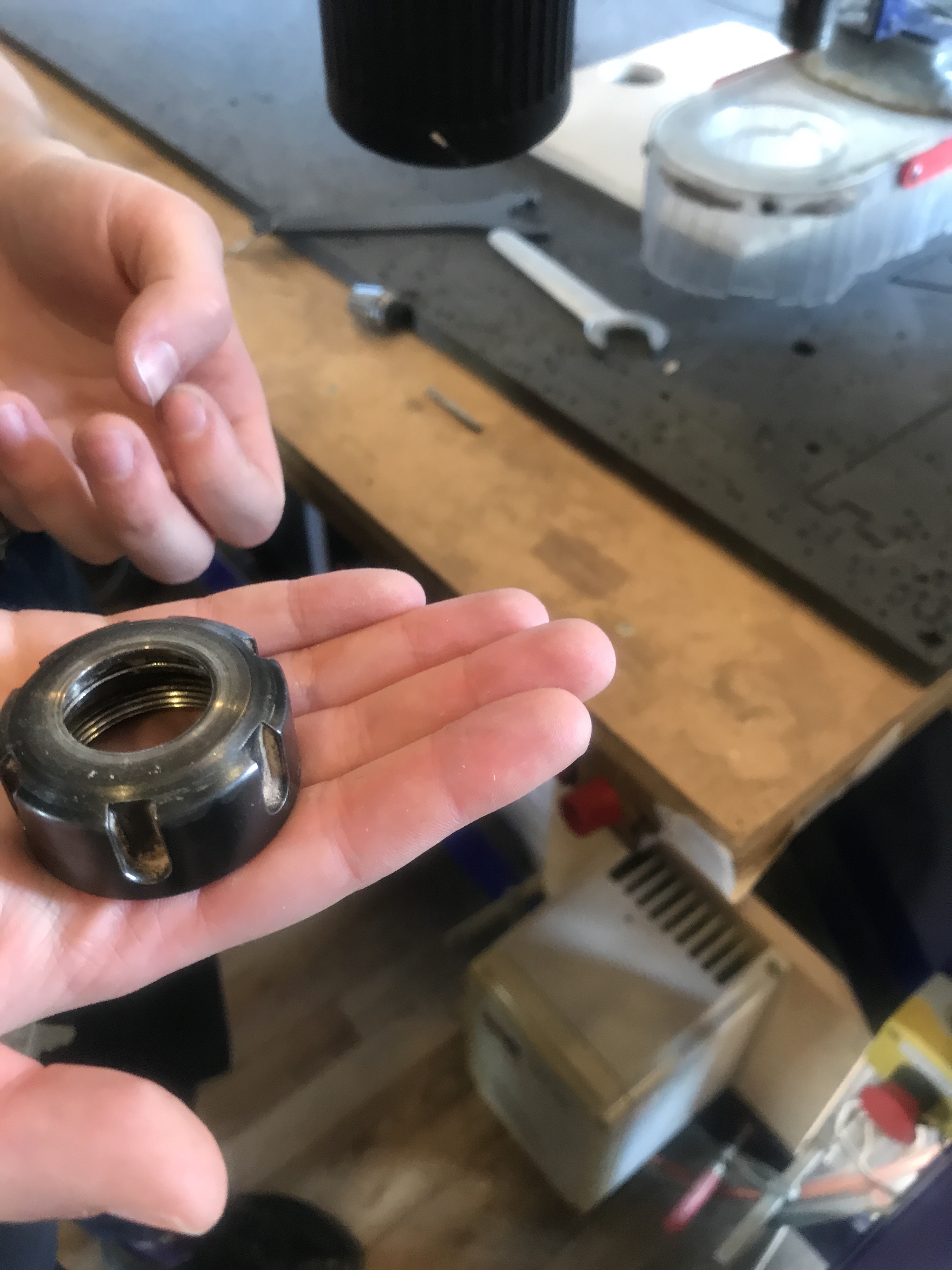 Remove dust
Collet
Depending on the diameter of the milling bit you’re using, you need a different collect, which holds the milling bit inside the nut of the milling head.
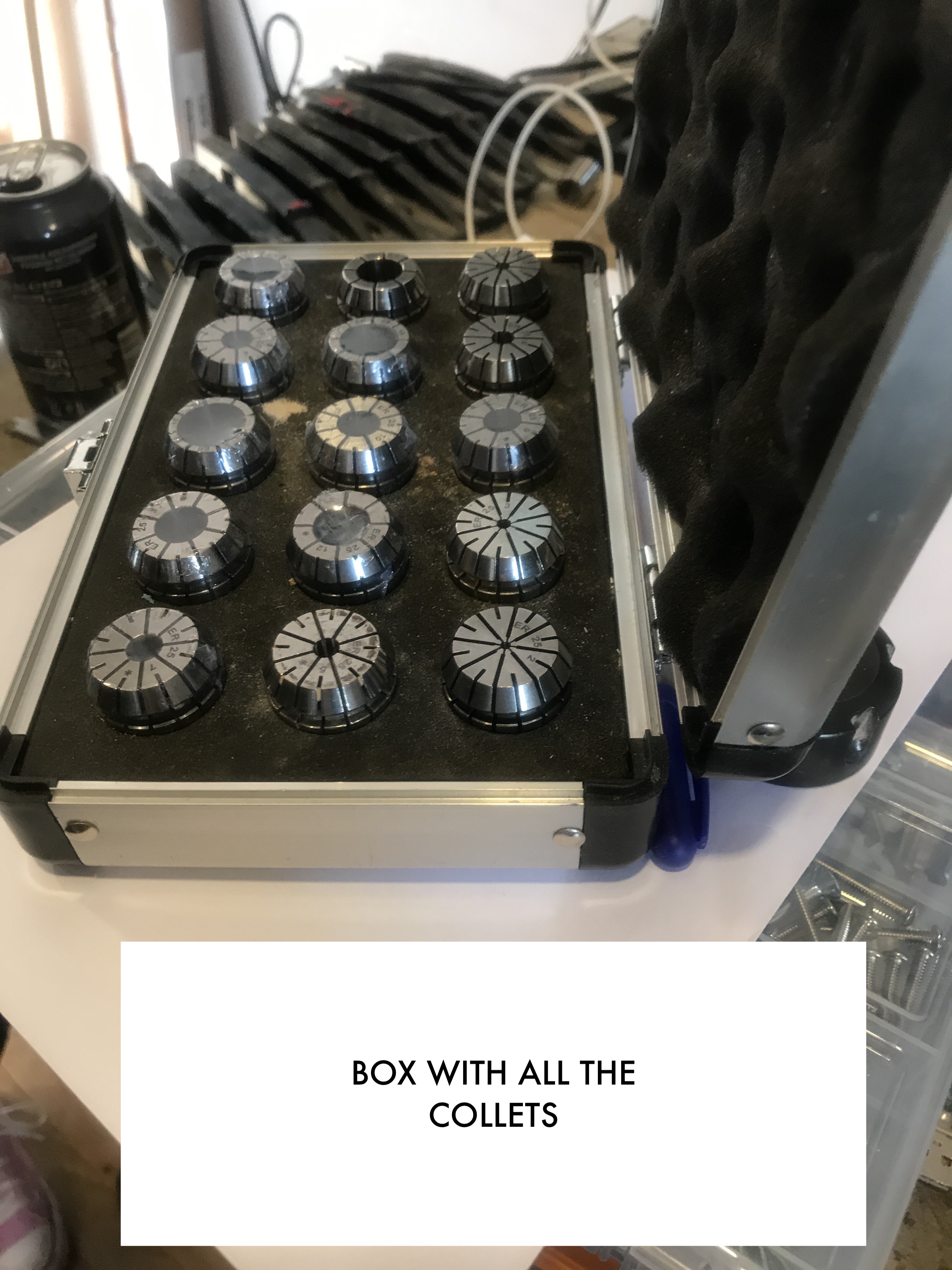 A case with different diameter collets
-
Put the nut inside the collet and millig bit inside the nut. The collet should click once its inside the nut. The milling bit should be pushed into the collet for about 2 cm.
-
Make sure to measure how far the milling bit sticks out of the nut+collet. It needs to stick out at least as far as the deepest point that you want to mill, and preferably 2-3 mm more.
-
Make sure that bit’s top is coincident with the inner part of the nut
 Don’t try to push the boundaries
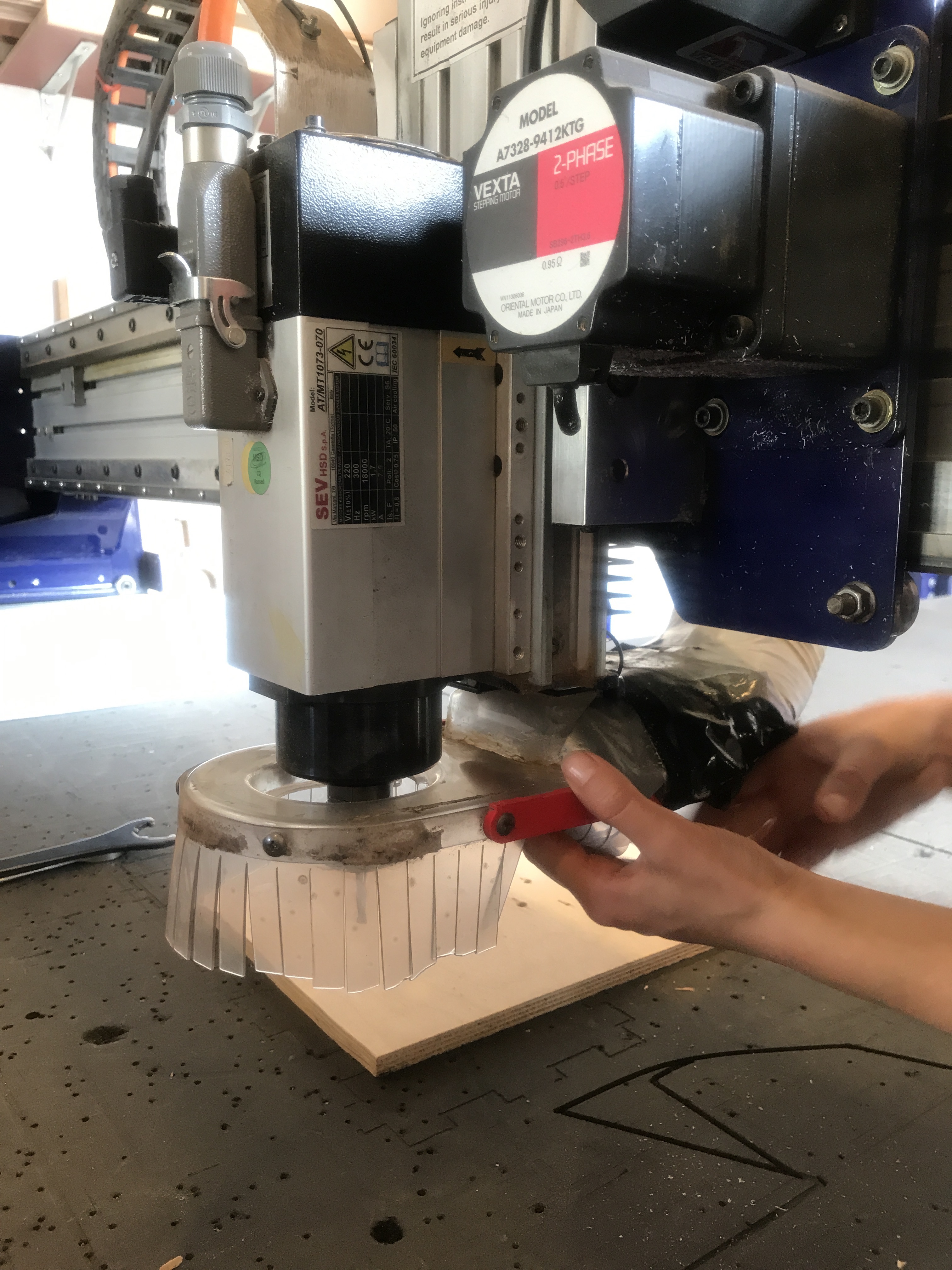
To attach the nut back in, screw it so its tight, then loosen the wing nut on the dust skirt then push the skirt down.
The skirt
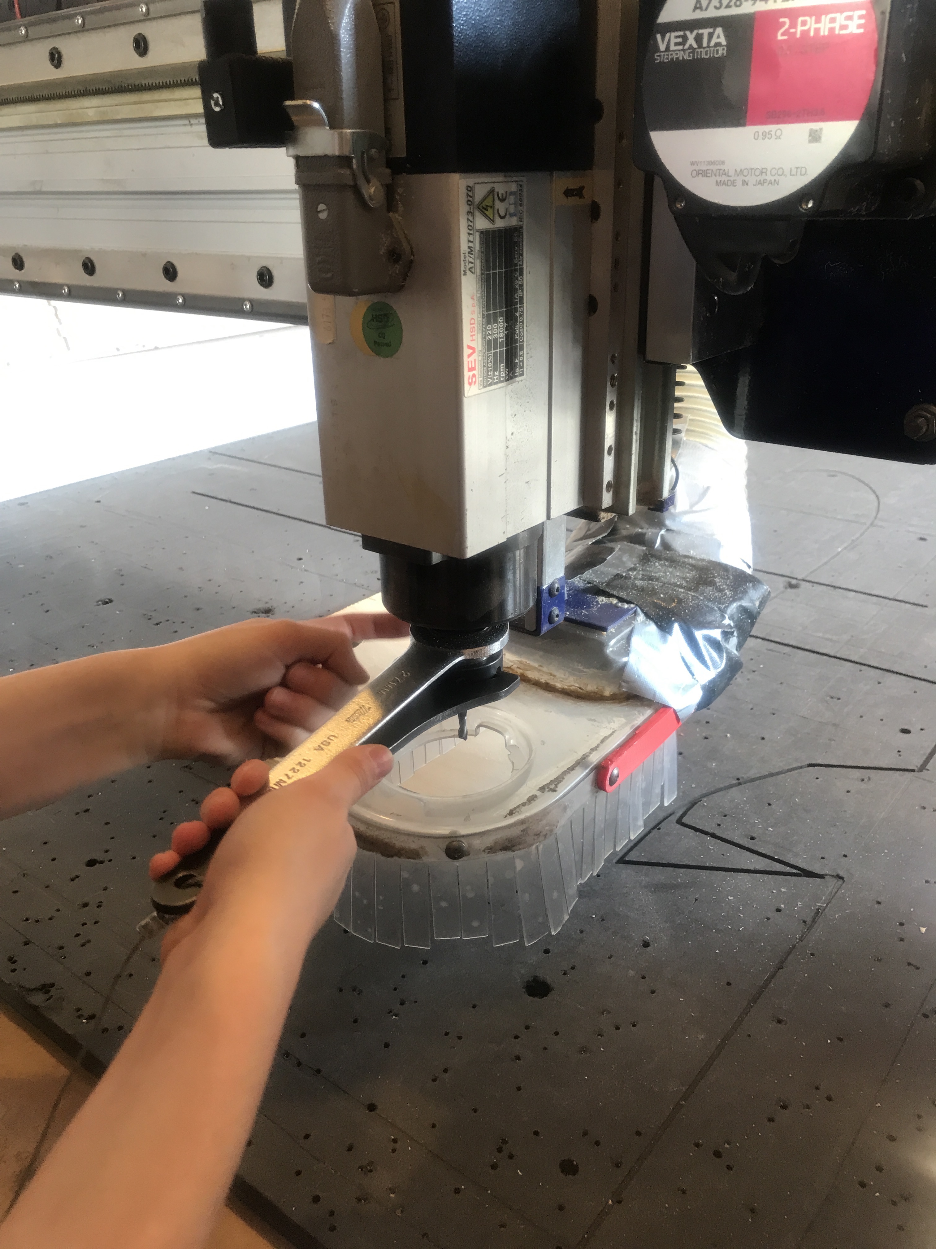
- Unscrew the dust skirt using the butterfly key located at the back of the Z-axis bridge. In this way, the Spindle will be accessible to attach the previously assembled components.
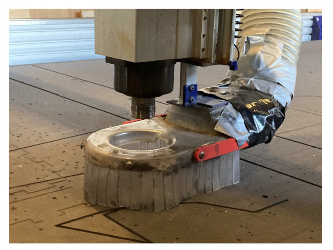 Dust Skirt
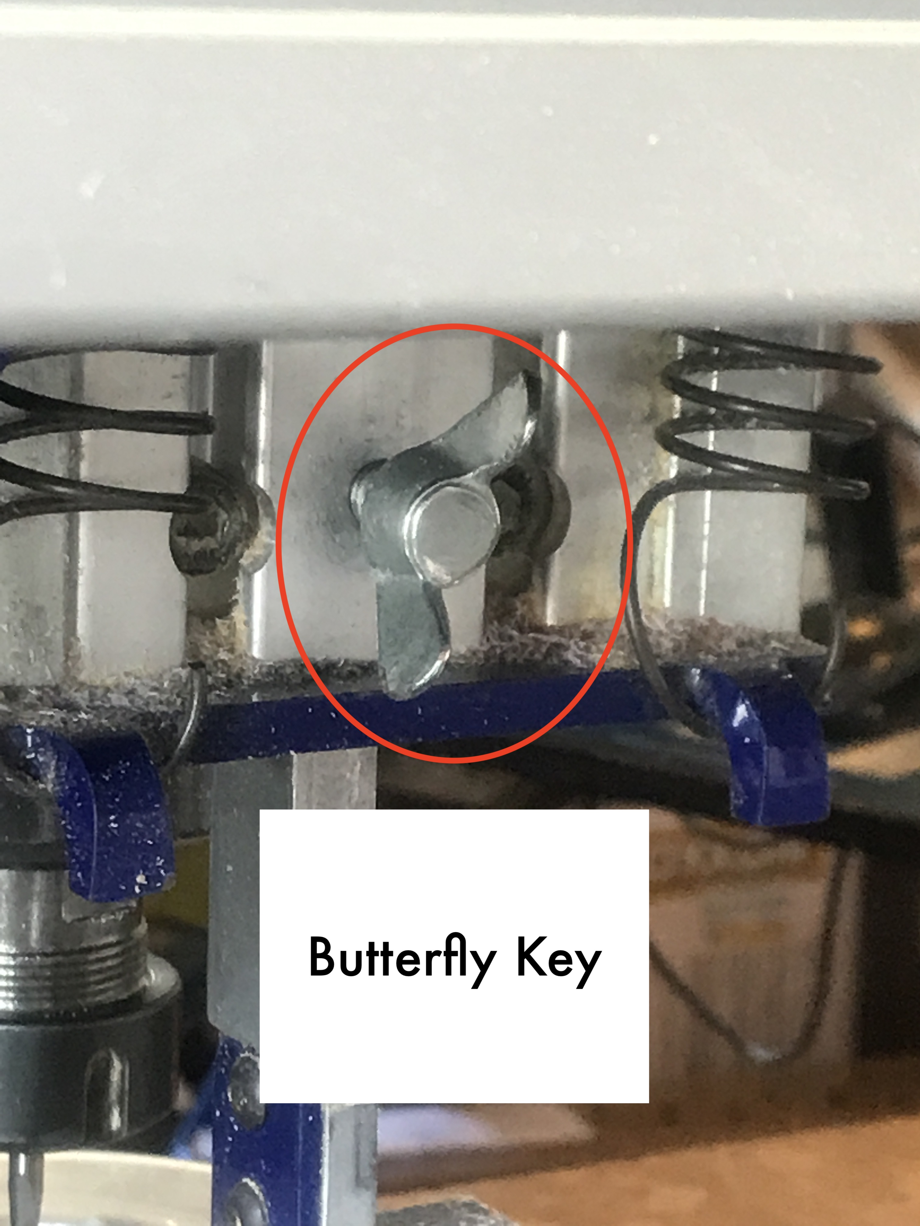 Butterfly Key
**Tip : You can use both screws to add more weight in case it’s too tightened (while removing)
 Loosning skirt
- Tighten the three components (collet,nut & milling bit) to the Spindle by use the key attached to the chord. Don’t over do it though, as then it would be hard to remove it later.
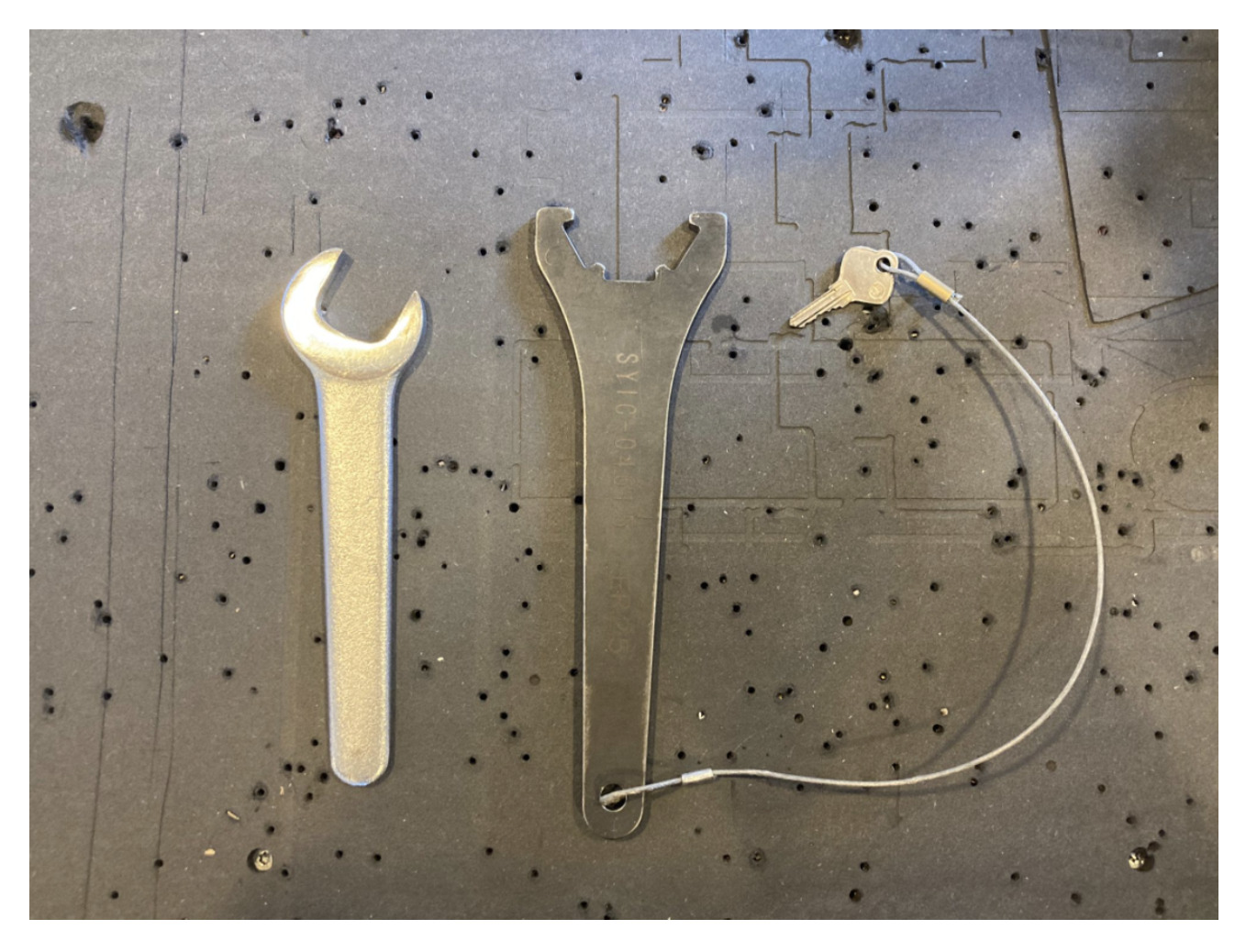 Key and Spindel
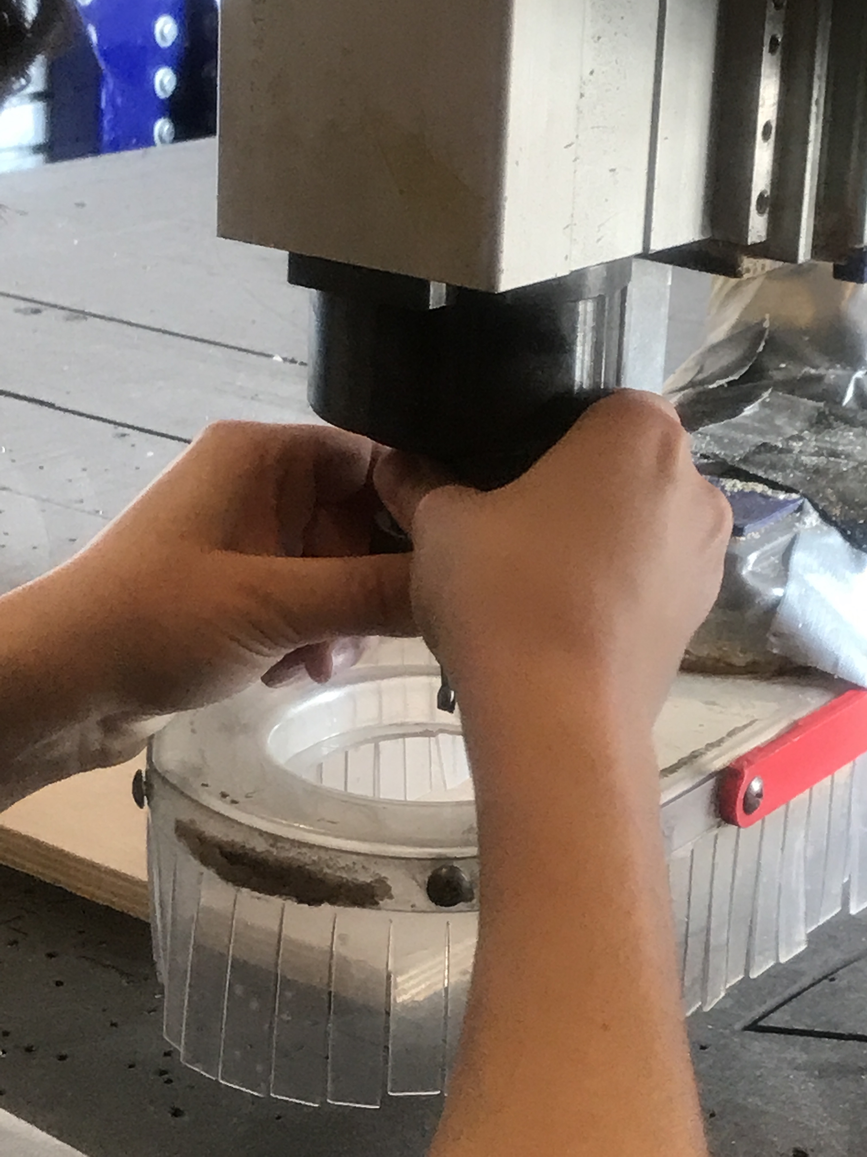 Putting back the three components
- Put the skirt back on - al the way
-
Place material on the machine. Make sure surface underneath is flat.
-
When using small pieces of wood : use drill to secure a screw so the piece doesn’t move when milling the drilling toolpath. Keep in mind, not to do it on a place where the milling bit is going! Make sure material doesn’t lift. keep number of screws used in mind.
Back to VCarve Pro
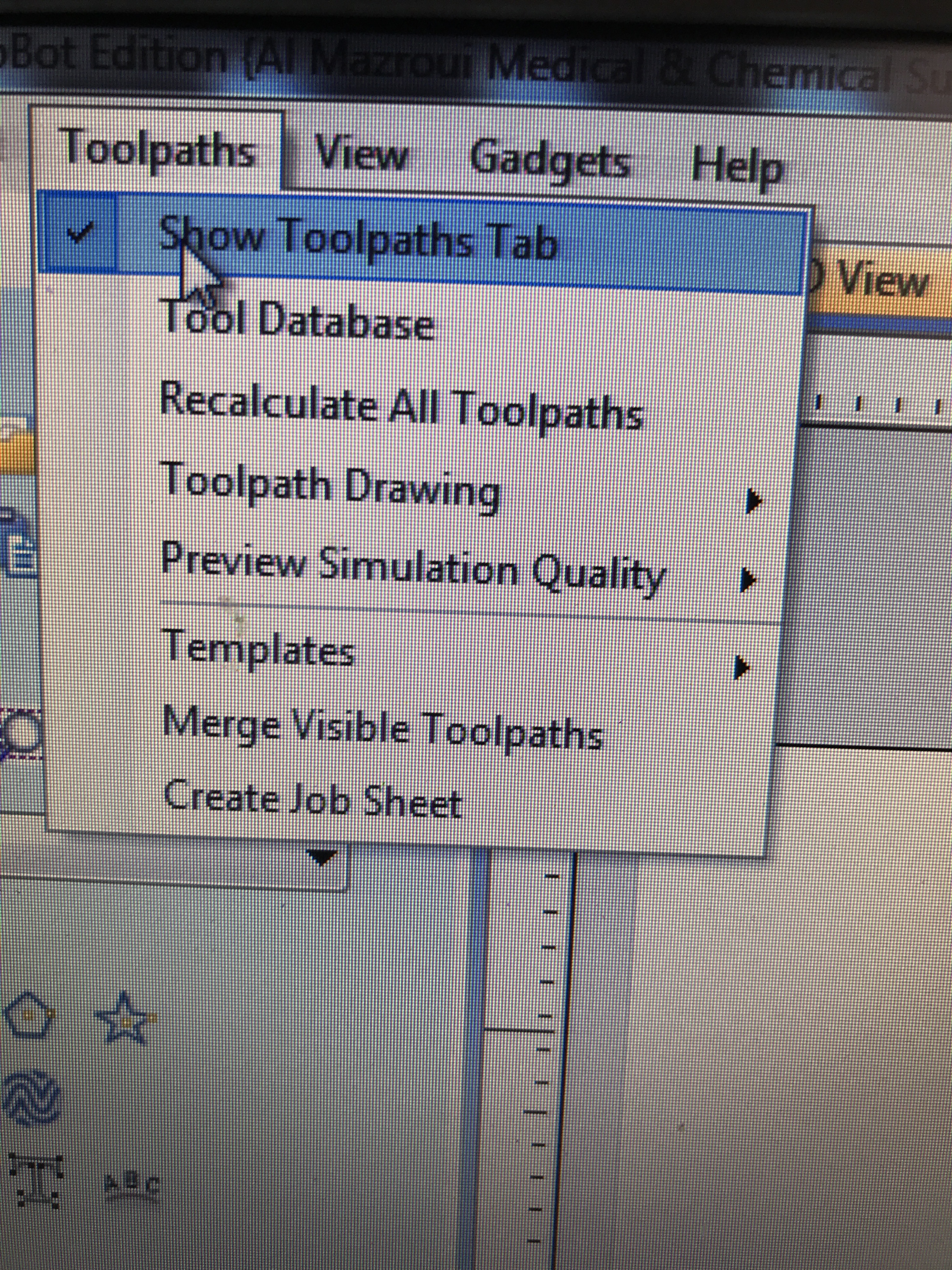
Toolpath menu
The ultimate purpose (in almost all applications) of VCarve Pro is to allow you to generate toolpaths which can be run on a CNC machine to machine the finished part of the material of choice. This requires, at a minimum, some vectors to describe the area to which a toolpath will be limited to or perhaps a combination of both vectors and 3D Model
Create the toolpaths
- Open the toolpath menu
- We created different toolpaths for the milling.
The order of the toolpaths should be as follow :
- Drilling toolpath
- Pocket toolpath
- Profile toolpath : Inner & Outer cutting toolpath
Drilling toolpath
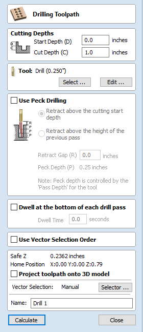
Use this toolpath to make holes for your screws to hold down the material when milling. Use the same size for the holes as for the mill. For instance if mill size is 5 mm then drilling hole size should also be 5 mm.
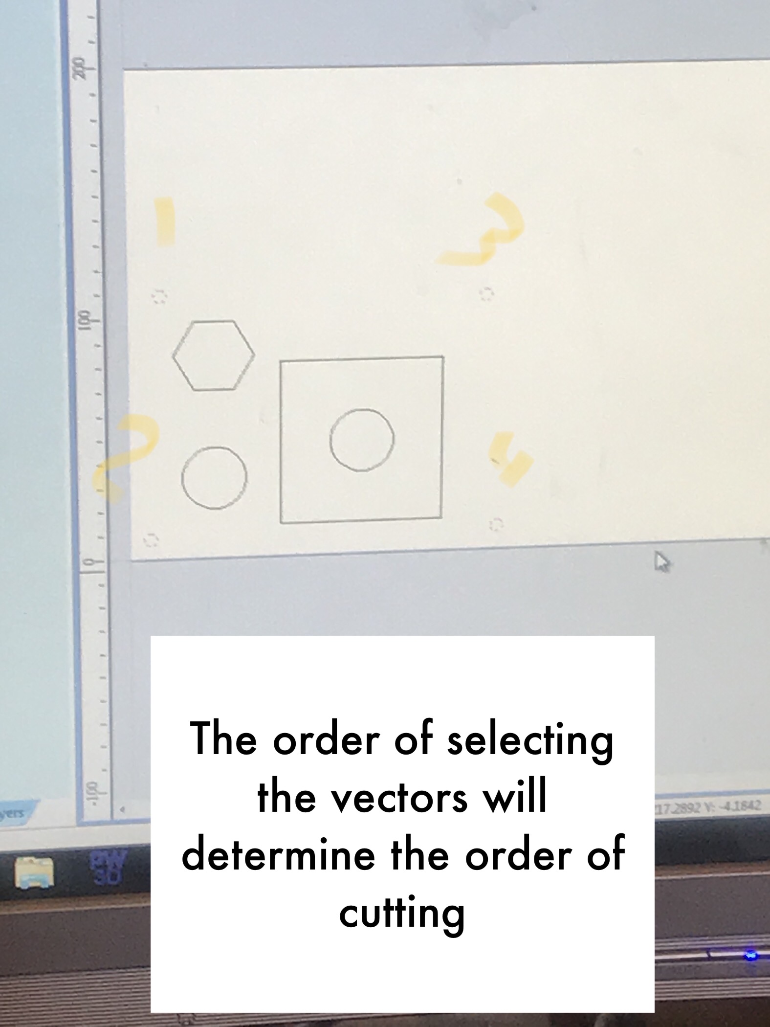
- Select the drilling holes. (When using the vector selection order the machine will mill the holes in the order of selecting)
Set start depth and cut depth
Start depth - This specifies the depth at which the toolpath is calculated from. If starting on the top of the material which is in most cases, then the start depth is 0. Only when drilling in a pocket, with our example we started with 5 mm instead of 0. A pocket is a way to make an engraving.
Note : If machining into the bottom of an existing pocket or 3D region, the depth needs be entered.
- Cut depth - The depth of the toolpath relative to the Start Depth. You don’t want to cut all the way through because you want the screw to hold onto something. (2/3 of the material thickness is sufficent, otherwise the material might move alot)
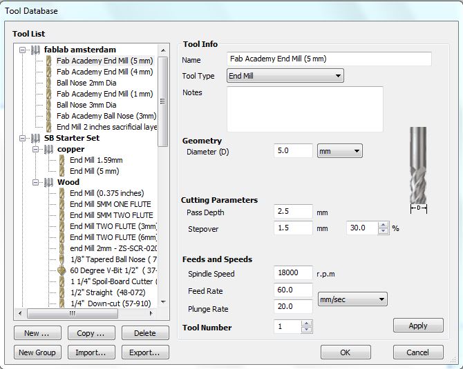
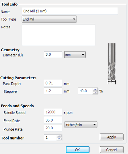
Select the tool (mill) - Clicking the Select button opens the Tool Database from which the required tool can be selected.
The settings we chose :
Tool info
- The name of the tool, we chose Fab Academy End Mill(5 mm) for our purpose
- Tool type - end mill
- Drilling tool path - end mil
Geomtry
Diameter - Diameter of the mill using.
Cutting Parameters
Pass Depth - Depth for every vector per pass (you always use multiple passes). To measure the pass depth, the rule of thumb is to use half of the diameter of the mill, for instance, if using a 5mm mill pass depth is 2.5
Step Over - Distance between each pass of the machine tool head. The larger the step over, the faster the job but the less precise it is. 100% step over means no overlap. 50% is half overlap. The lower the step over, the smoother the surface.
Larger stepover : rough milling which is used for fast prototypes.
Small stepover : nicer material & finish, will have precise results.
30% is roughlt in the middle - Good Startpoint
Feeds and Speeds
Spindle Speed - 1800 for wood (maximum speed).
Feed Rate - is the speed of the machine, 50 - 60 mm for wood with 2 flutes end mill. Smaller diameter runs slower. IF using foam 100-120 mm per second is fine. A bit of trial and error to get better results
Plunge Rate - Plunge rate is the speed at which the router bit is driven down into the material when starting a cut and will vary depending on the bit used and the material being processed. Always keep it on 20.
-
Peck drilling -
-
Dwell at the bottom of each drill pass - the Dwell Time value is used pause the drill at the bottom of each peck drill pass before retracting. The dwell time value is measured in seconds.
-
Use vectors selection order and select the shapes in the order you wish for them to be cut
- Press Calculate and close.
Preview Toolpath
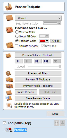
Reset preview - Reset the preview before running. The toolpath boxes have to be checked to run with Preview Visible Tool Paths. This will demonstrate the order of cutting as well as the depth, for instance to show that the mill will not go all the way through.
Pocket toolpath
Pocket milling allows the machinist to use an end mill type cutting tool and machine away large amounts of material in a “Roughing” cycle prior to finishing the part. This saves time and efficiently maximizes the amount of material removal. There are different styles of pocket toolpath that include traditional lace or zig-zag (back and forth), concentric or offset In/Out and high speed cutting paths
-
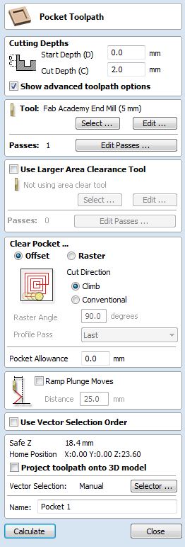
Set Start depth (We went for 0) and Cutting depth (We went for 6).
-
Select tool (We chose Fab academy end mill 5 mm from tool list)
-
Clear pocket
There are two choices of the type of fill pattern that will be used to clear away the area to be machined with the Pocket Toolpath
Offset : Calculates an offset area clearance fill pattern to machine inside the selected vector(s). It works well with vectors, yet not with 3D shapes.
Raster : Calculates a Raster based area clearance fill pattern to machine inside the selected vector(s).
Cut direction : Climb or Conventional, choose either one, won’t affect the final result.
-
Raster Angle - Between 0 and 90°, where 0° is parallel to the X axis and 90° parallel to the Y axis.(We chose 90 because it is less harsher on the machine)
-
Profile Pass - Used to clean up the inside edge after machining the pocket. This can be done either before the rastering (First) or after the rastering (Last). (We used Last because it gives a cleaner edge).
- Advanced Settings
Vector selection order gives you more control of what you are doing.
- Pocket Allowance - The Pocket Allowance allows you to quickly create a toolpath that will machine the pocket either smaller or larger than the defining closed vector. A Pocket Allowance of 0.0 (the default) will create a pocket the exact size of the defining vector.
This helps in making the design press fit and is similiar to the offset command as in milling the pcoket either smaller or bigger than the vecor, to make things fit either tightly or loosely.
- Close
Profile toolpath
Profile Machining is used to cut around or along a vector.
Profile toolpaths can be outside, inside or on the selected vectors, automatically compensating for the tool diameter and angle for the chosen cut depth.
- Note : the program will always cut the inner vectors before the outer vectors to ensure the part remains attached to the original material as long as possible.
Cutting Depths
-
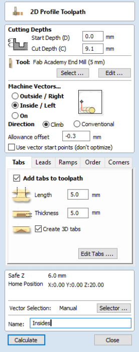
Start depth : Specifies the depth at which the Profile toolpath is calculated. When cutting directly into the surface of a job the Start Depth will usually be 0. If machining into the bottom of an existing pocket or stepped region, the depth of the pocket / step must be entered. (We went for 0)
-
Cut depth : The depth of the profile toolpath relative to the Start Depth. (We went for 12.4)
-
Tool - click on select to open up the tool database, which includes some advanced toolpath options
- The Tool Database
Tool info
-
Name - choose a name for your tool
-
Tool type - as explained earlier there are various cutters that can be specified in the database, choose the one you intend to use.
Some examples :
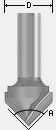 V-Bit
V-Bit
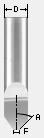 Engraving
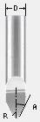 Engraving
 Engraving
Geometry
- Diameter - the diameter of the tool. The tool image will indicate where this dimension is taken from.
Cutting Parameters : The maximum depth of cut the tool can cut. The Pass Depth controls the number of z level passes that are calculated for a toolpath.
- Machine vectors - basically where to place the mill
There are 3 options to choose from to determine how the tool is positioned relative to selected vectors :
-
Outside - calculates a profile toolpath around the outside of the selected vectors, cutting direction either climb or conventional.
-
Inside - calculates a profile toolpath around the inside of the selected vectors, with the options for the cut direction to be either climb or conventional.
-
On - Calculates a profile toolpath around the On selected vectors.
Direction - can be set to either conventional or climb, doesn’t make much of a difference.
Allowance offset Either Overcut (negative numbers will cut smaller) or Undercut (positive numbers will cut larger) If the allowance is set to zero then the toolpaths will machine to the exact size.
- Sperate last pass - A seperate allowance can be specified for the last pass. If this allowance is given all but the last pass will be undercut by the specified allowance with the final pass being the only pass which cuts to size.
Note : If the Reverse direction button is checked, then the cutting direction of the last pass is reversed.
-
Tabs !!important!! (bridges) are added to hold parts in place when cutting them out of a material. You can edit the tabs to locate them in a centered position in each side of your design. Use as much as you need depending on the size of your design. Yet avoid placing tabs on corners, you can add tabs automatically or manually.
- Press calculate
- Save
After creating toolpaths
-
Rename ToolPath list, make sure that each path is seperate from the others especially the drilling toolpath and saved on its own layer. Not to have accidentelly selected a screw hole in another layer.
-
Tip : When saving files, order them in this order : Drilling toolpath > Pocket Toolpath > Profile toolpath. The machine will follow the order given and this way you avoid making mistakes.
-
Note : Double check that there are no objects hiding, avoid copy pasting little pieces
-
Clock icon - (Tool path summary) will indicate how long the milling is going to take
-
Floppy icon - Save toolpaths Save files separately. Set metric system. Save file in map.
-
Make sure not to change anything after calculating, always re-calculate to be on the safe side. Also watch the 3D view to make sure everything is fine.
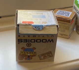
- Note : When using nails, woodies are better because they don’t break!
Operating the machine
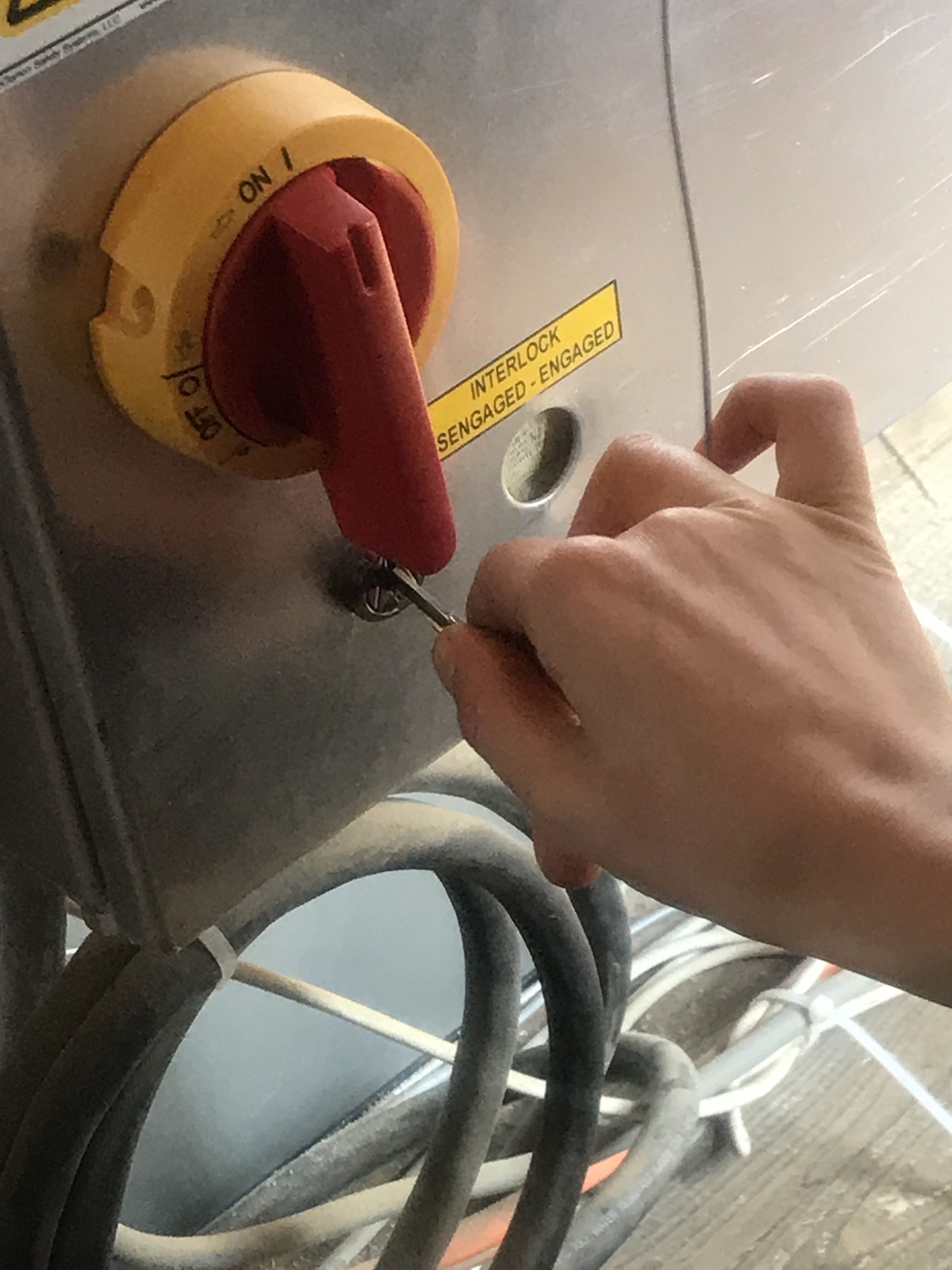
- Turn on the red button on the side of the machine.
-
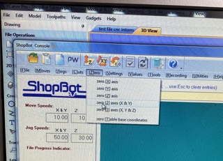
Open the software that is linked to the machine. It is called shopBot V3
-
Close the little window the pops up, not needed.
-
Locate keypad, press K on keyboard
-
The arrows on keypad or the arrows on keyboard (down arrow is X and up arrow is Y) are a way to move milling head, keep X and Y axis in mind when moving. You can move the Z axis with page up & down on keyboard.
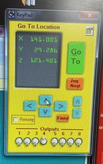
- Caliberate the machine, find absolute zero (press zero X/Y button) then press ok.
-
Press K on keyboard and move mill head to the material origin (bottom left - check file)
-
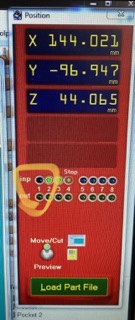
Take a picture of the coordinates - in event o a power shortage/emergency button press etc; you will need to re-enter the origin
-
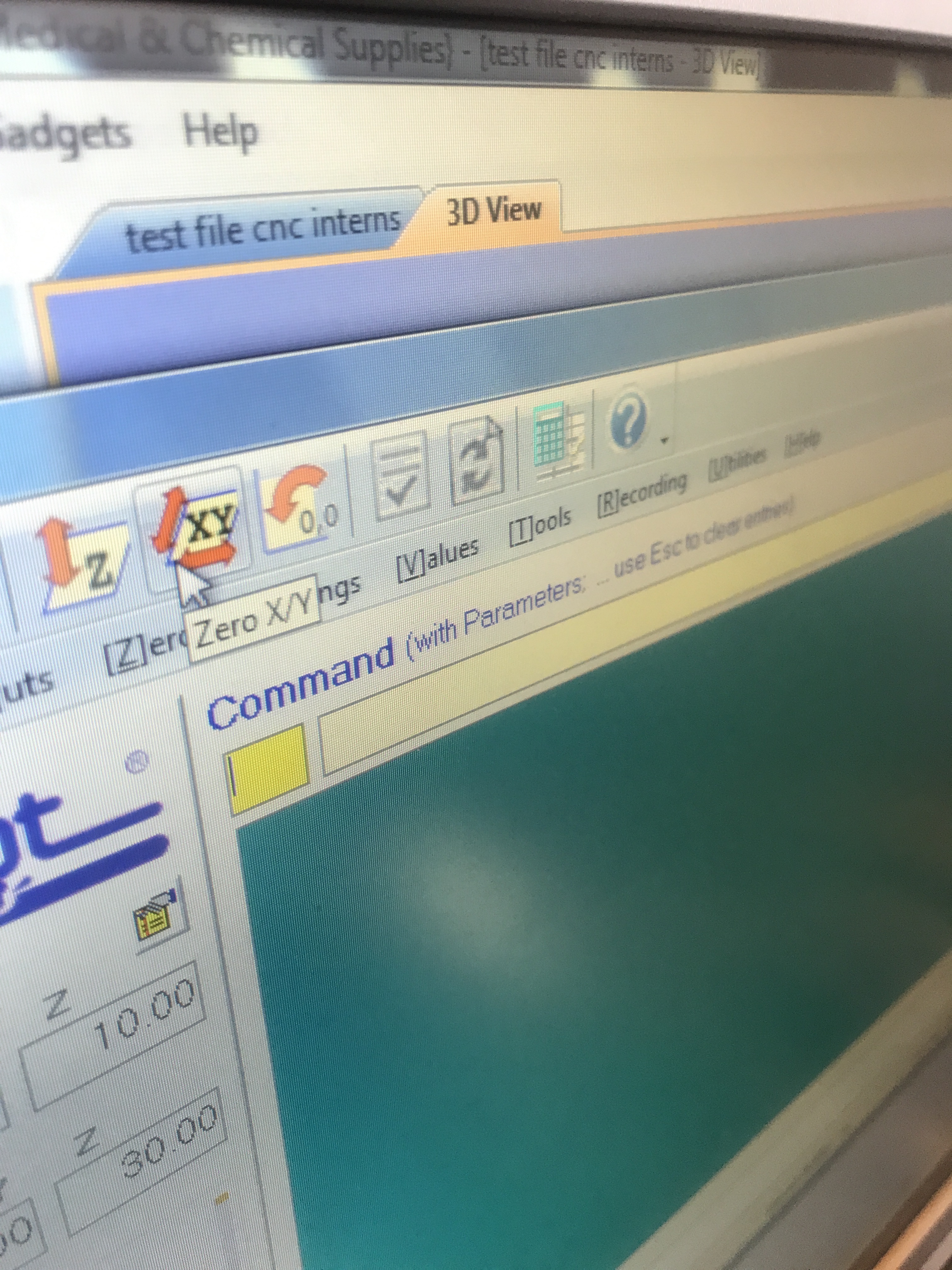
Open tab Zero > click zero [2] axis (X & Y), this is now our new home
- Zero the z-axis. Zero on table surface using the keypad since we put the zero in the file on the bottom. Choose a nice flat place. In short, to the bottom of the material
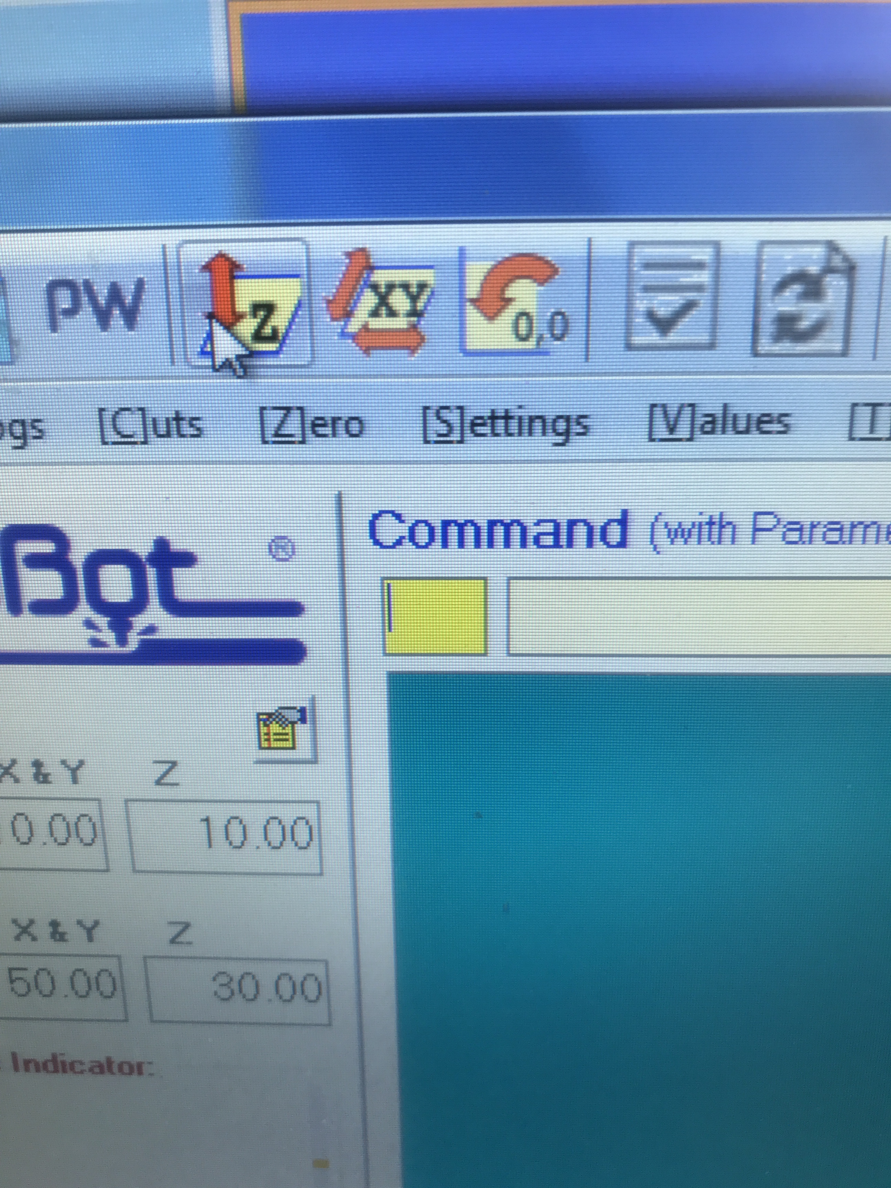
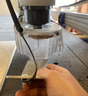
- Use the metal plate to check connection with milling bit. Check if inp 1 lights up. If Input one lights up, then there is a connection. This will help to spicify the depth
-
Put metal plate directly under milling bit.
-
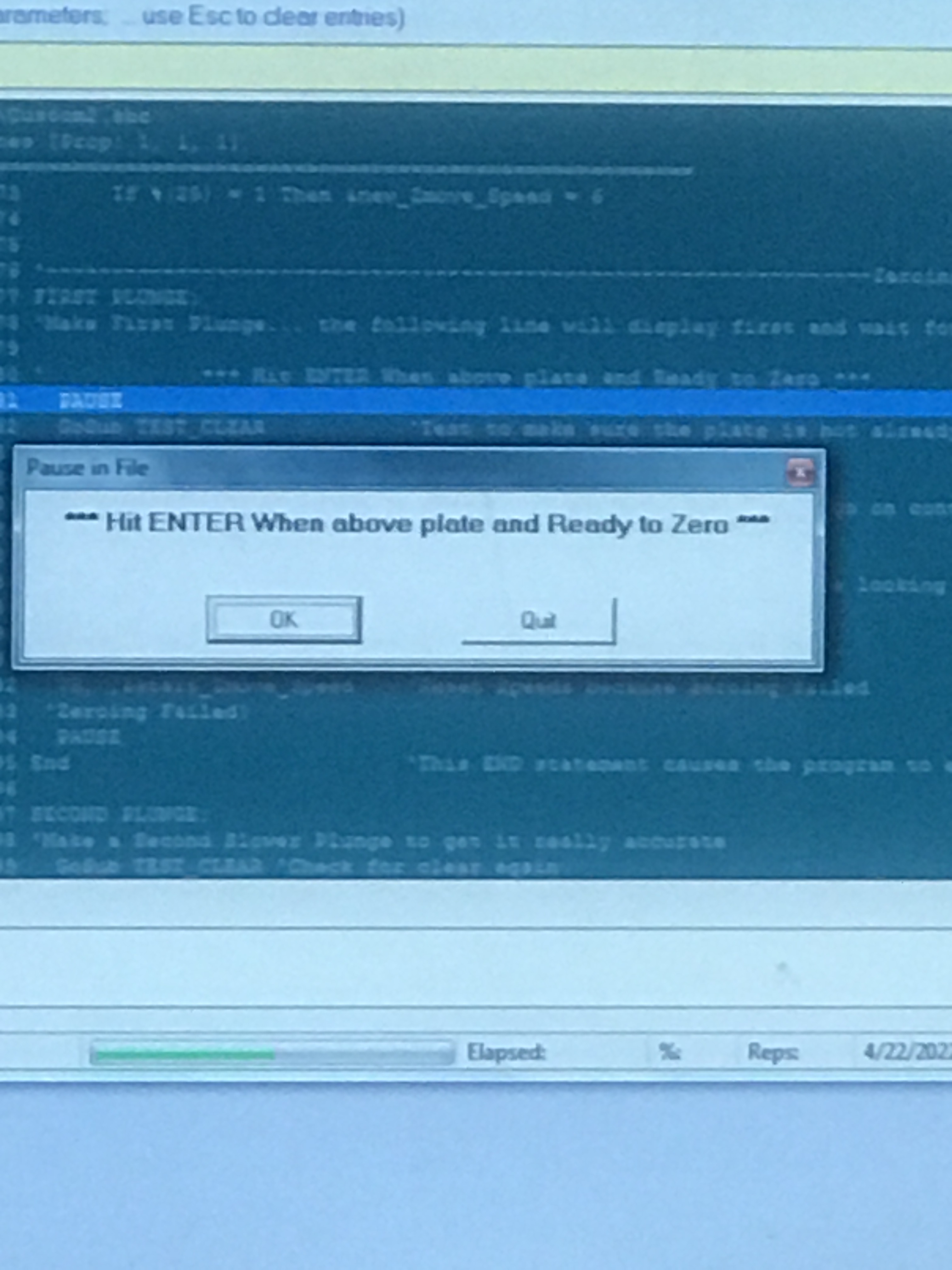
Press ok, don’t remove the aligator clip. Ready to zero
- Open keypad with K. Press page up ! No other button ! To move the milling head up.

-
Put away metal plate.
-
Check file one more time.
-
Load file - open the screw toolpath file.
-
Use key to turn on spindle
-
Take a look, make sure it is not dancing around and that everything is ok.
-
Turn on ventilation (back of the room)
-
Put on googles
-
And when completely ready press Start
- Holes will be drilled
Stay close to space bar incase anything goes wrong, once pressed the mill will stop moving yet not spinning
-
Turn off spindle and ventilation.
-
Press K to open up keypad and move milling head to make space to put in screws.
-
Secure screws.
-
Recap from earlier… Woodies are better since they don’t break!
-
Load second file.
-
Turn on spindle (keep space in touch)
The remaining toolpaths will be milled.
After using the CNC milling machine
- Turn off ventilation and spindle.
- Move milling head.
- Take out screws and count how many you took out.
- Close the Shopbot software
- Switch the machine off
- Vacuum the table.
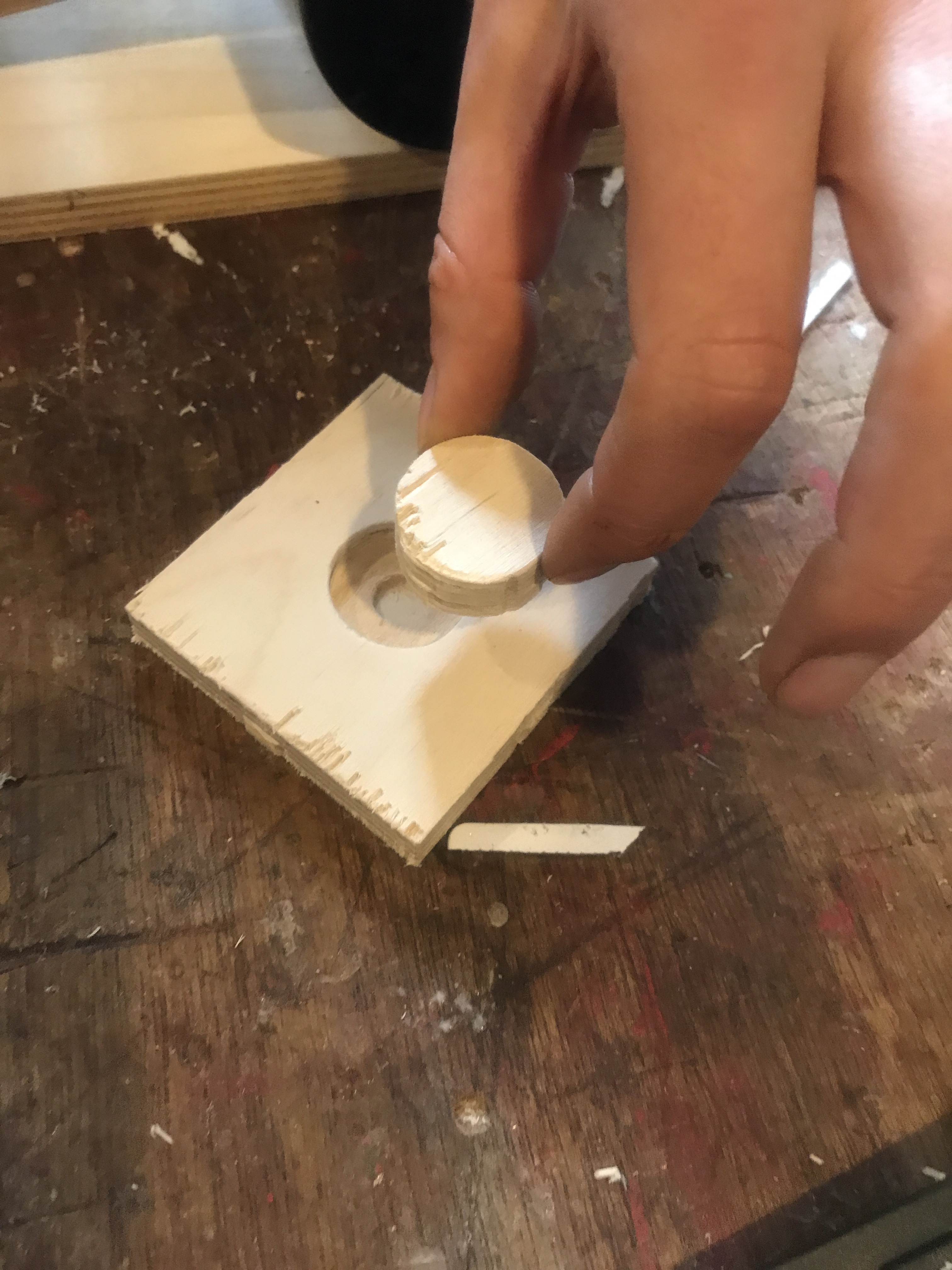 Final results after sanding