Intro
I started off by watching an intro on PCB on youtube https://www.youtube.com/watch?v=vaCVh2SAZY4
Some concepts :
- Surface Mount Technology (SMT) : the components are placed and soldered on one layer
- PCB stands for Printed Circuit Board which is a board or a card that electrically connects and mechanically supports electrical components
- The connections are made with conductive tracks/traces usually made out of copper
- The copper is laminated in between sheets of non conductive material like fiber glass and epoxy resin, the resin part is flame resistent and meets the flame retardant grade four standard (FR4)
- A thin sheet of copper is pressed and heated onto the substrate
- With the double or multi sided PCBs, A drill bores out a chunk of copper and substraye. Electroplating is the process of adding a think layer of copper.
- A solder mask layer is often added on most of the top of the board. lacquer like polymer is placed on places where we don’t want to solder components
- Solder Mask Keepout
- A layer of ink is added to help us identify our components
PCB Copper Plates Types
- When it comes to PCBs, the copper plates can be either one sided or double sided or even multilayered. Singel Sided has only one layer of conducting material on one side of the board. The single sided are one of the most commonly fabricated boards as they are very simple and basic to make.
There are four different layers :
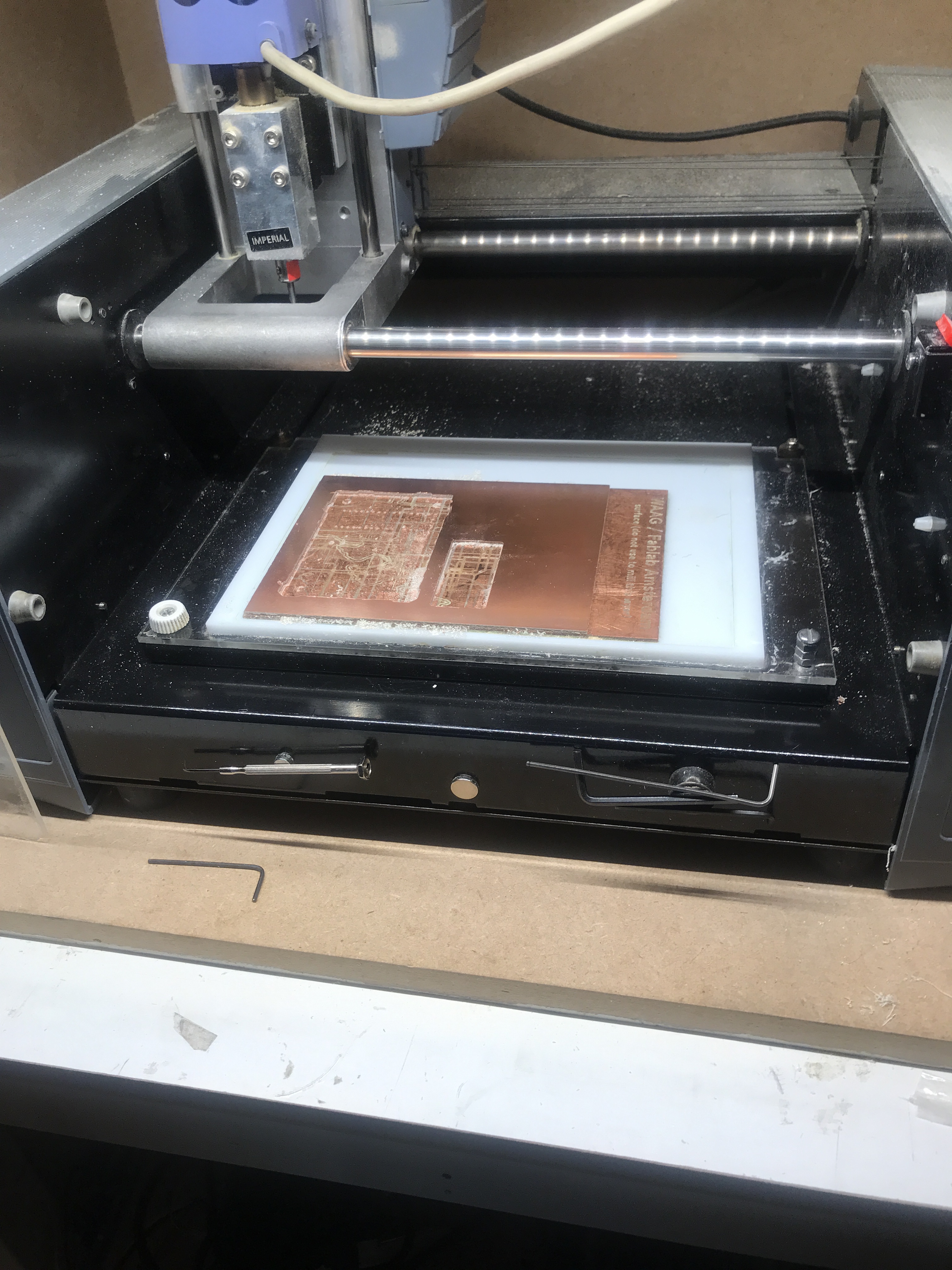
- Base layer that is screwed into the machine
- Acrylic white sheet on top of it
- Sacrifical layer on top of the acrylic one
- The copper plate is the last layer that will go on top of everything
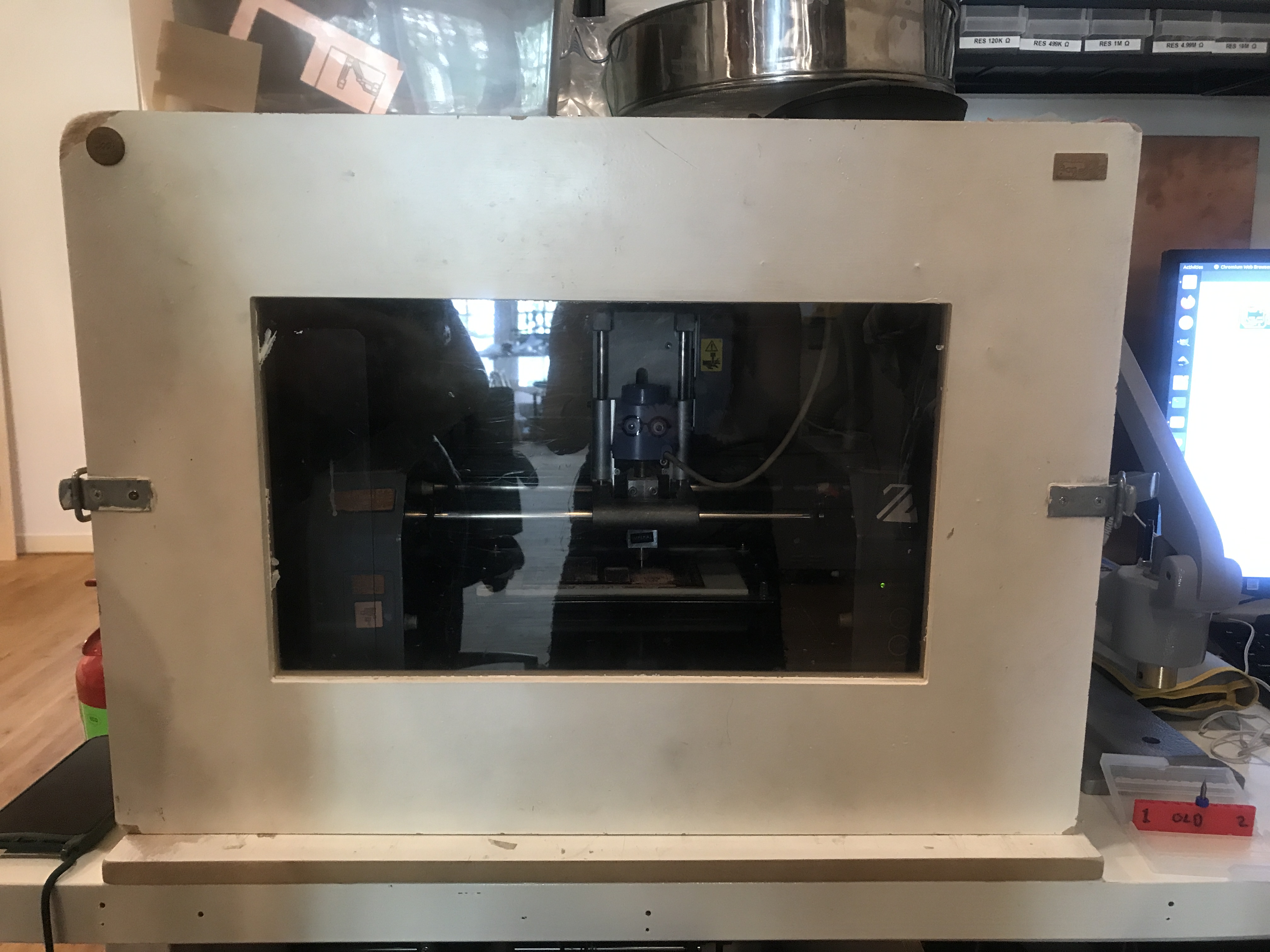
Tip : There is a light switch on the right side of the machine
Steps
- Make sure your file is exported as a png or svg. Using kicad you can export as an svg
- If there is an older board attached, remove it and clean the area with a sticker remover.
Note : When you setup the sacrifical layer, clean the area afterwards as well.
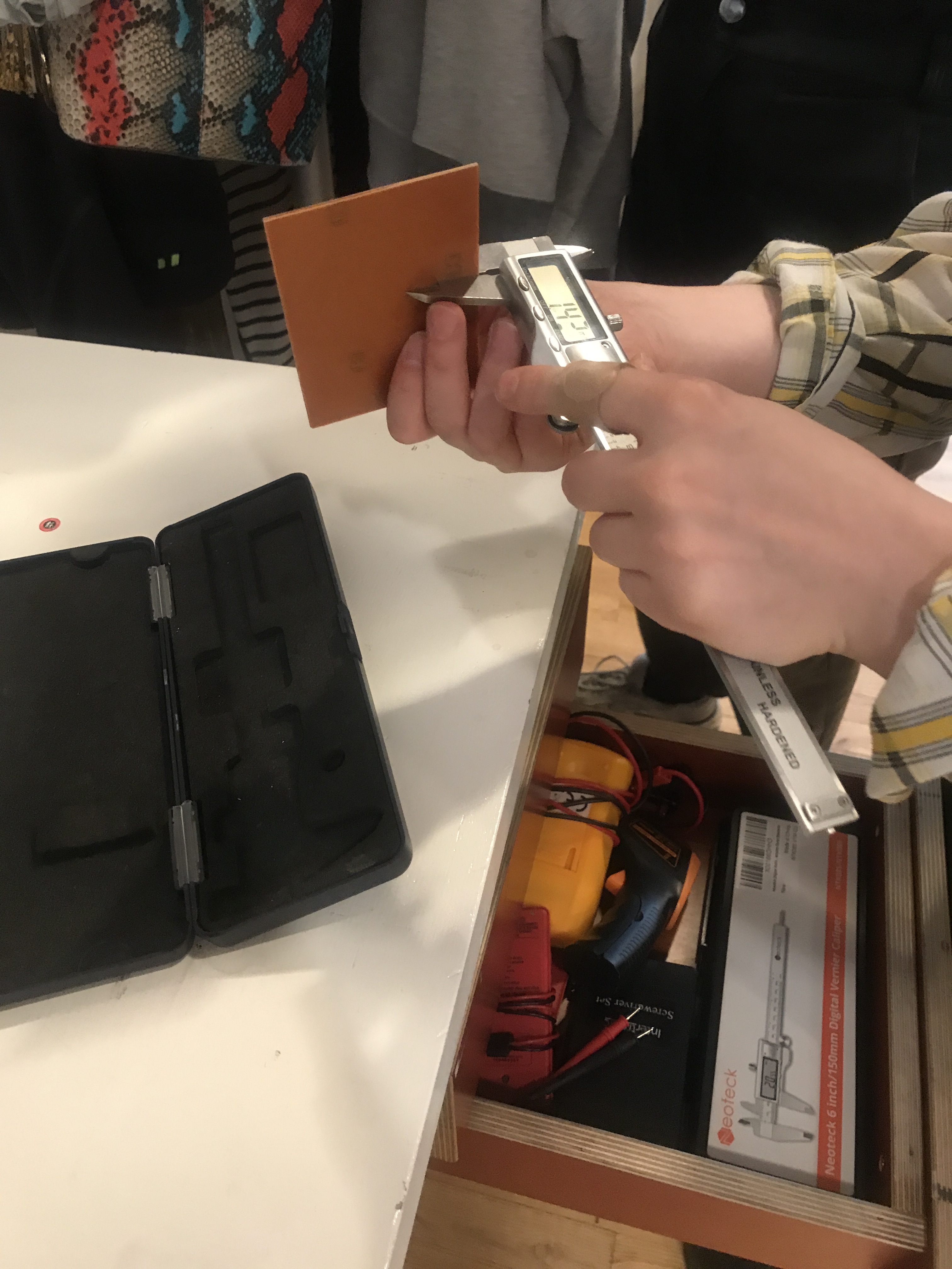
- Measure your copper plate
-
Remove bed from machine
-
Attach the copper plate with a tape and spread it on the surface everywhere, place the cooper plate on the sacrificial layer. Use a piece of fabric to press the plate.
Make sure it doesn’t overlap though
- Insert bed into machine & tighten by fixing screws
Types of PCBs :
The general umbrella
-
ISP which is In System Programming which is also called In Circuit Programming Is the ability of some programable logic devices, microcontrollers, and other embedded devices to be programmed while installed in a complete system. So, intead of needing the chip to be programmed before hand.
-
Types :
JTag stands for Joint Test Action Group SWD for programming chips called SAMD
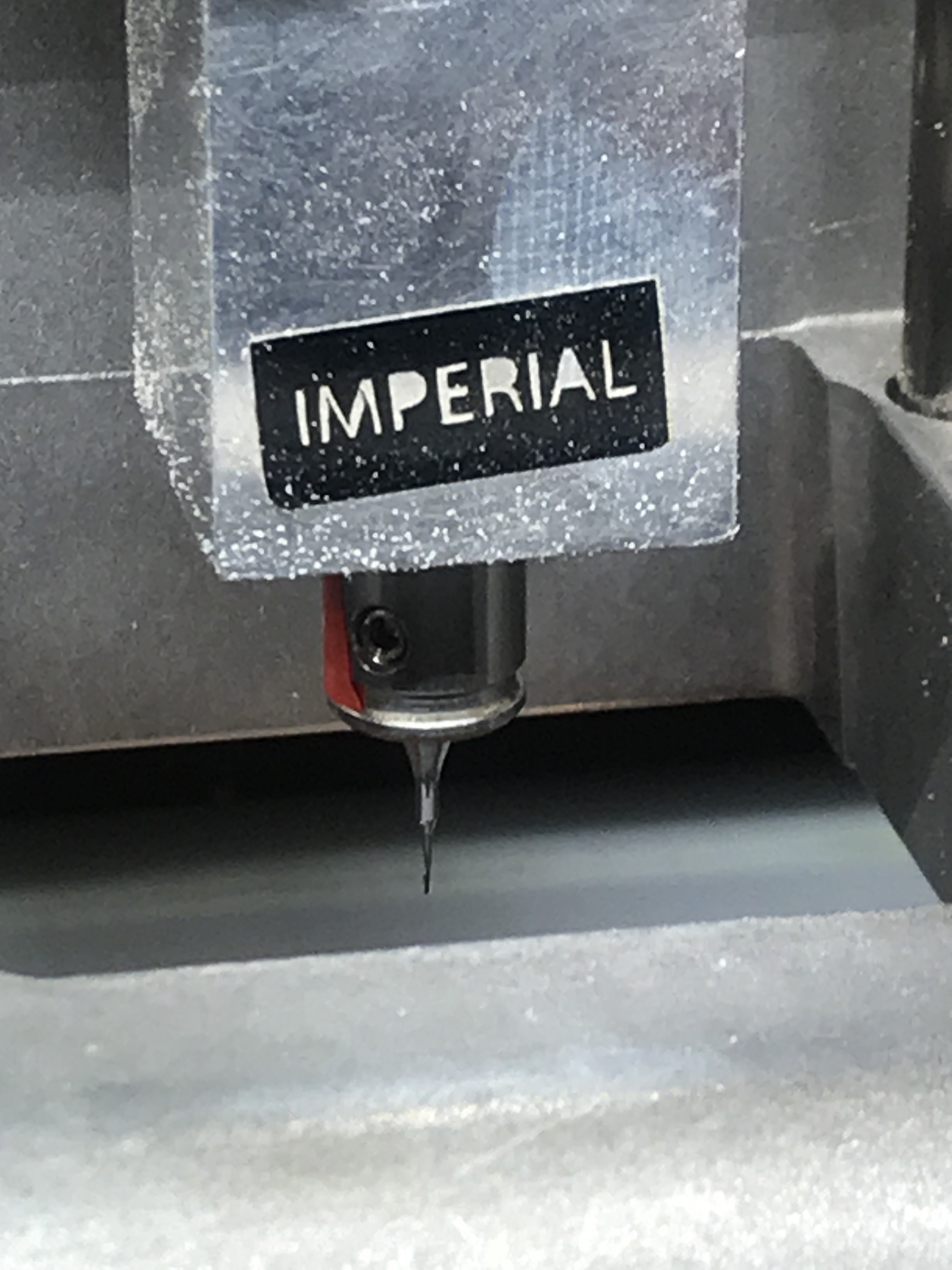
Insert Milling bit :
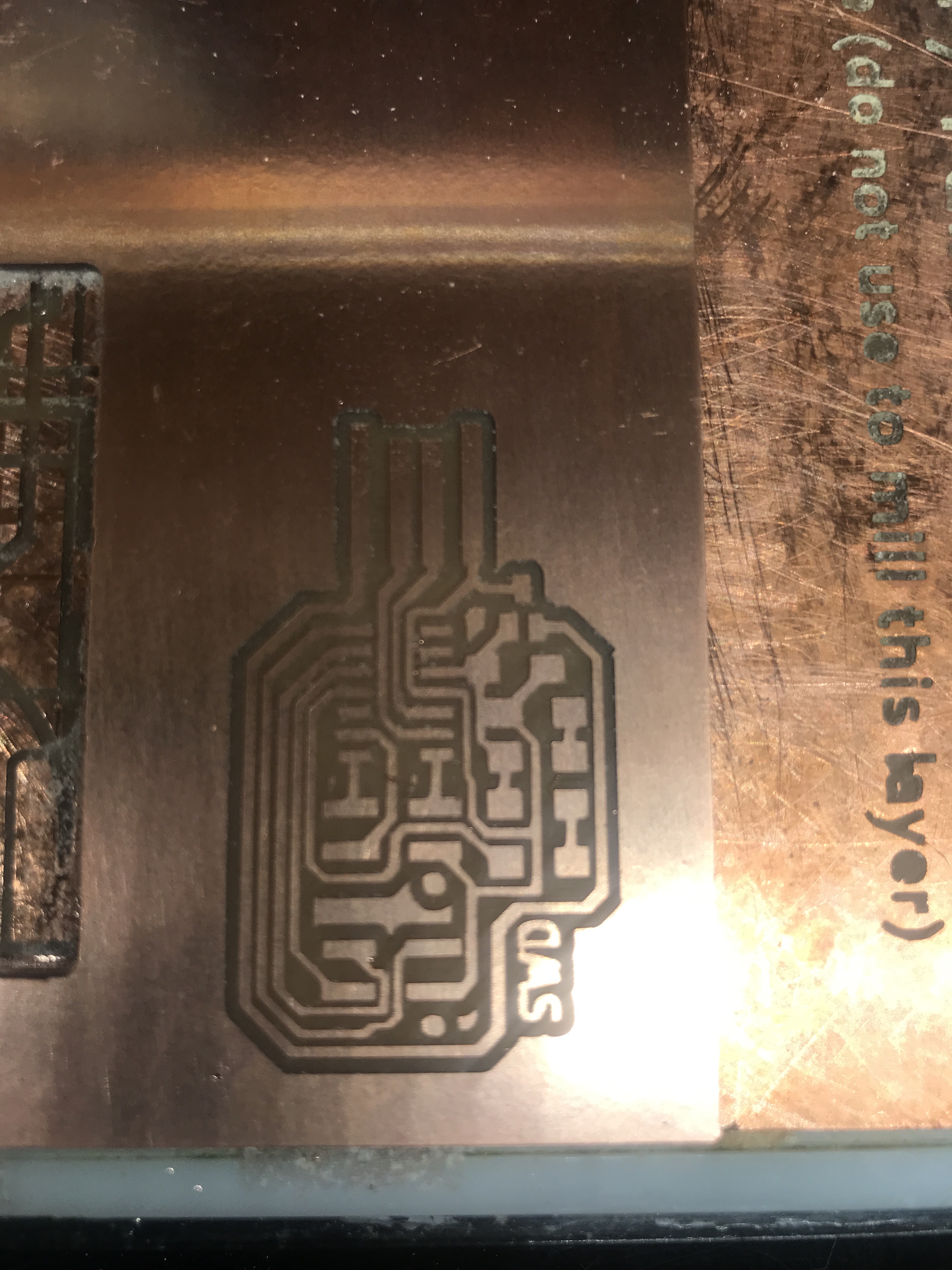
We used 0.8 mm milling bits for outlining & 0.4 mm milling bits for tracing
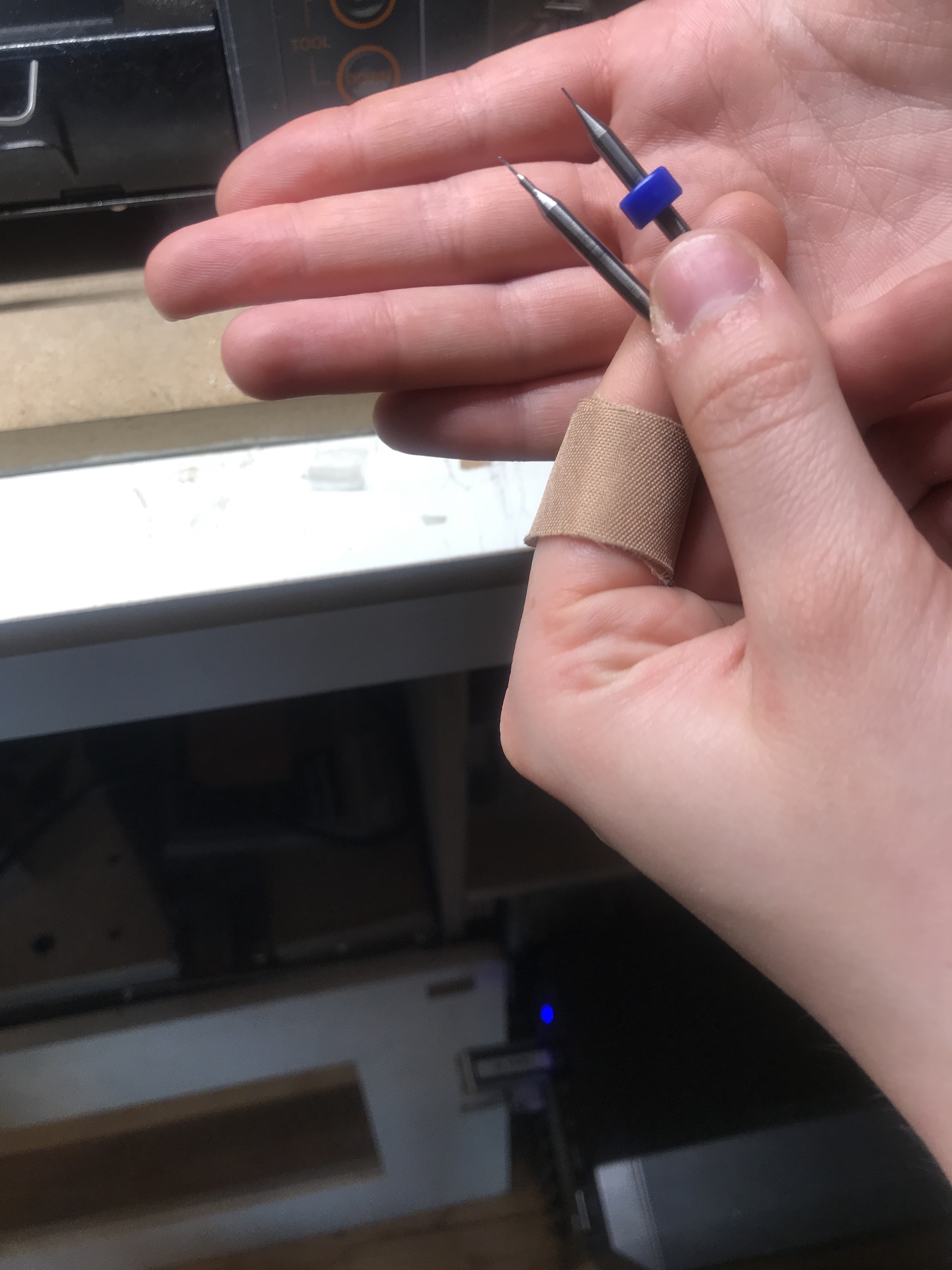
You can use either one or two flutes, yet two flutes are more precise.
 You can find milling bits over here, ask Hank or Michelle before using
Operating Software Steps :
- Turn on machine : Press power button in front of machine.
- Opening terminal (shortcut : ctrl+Alt+t)
- Start mods by typing : cd Mods bash Mods
- Click cancel & cancel again. This will automatically open the browser.
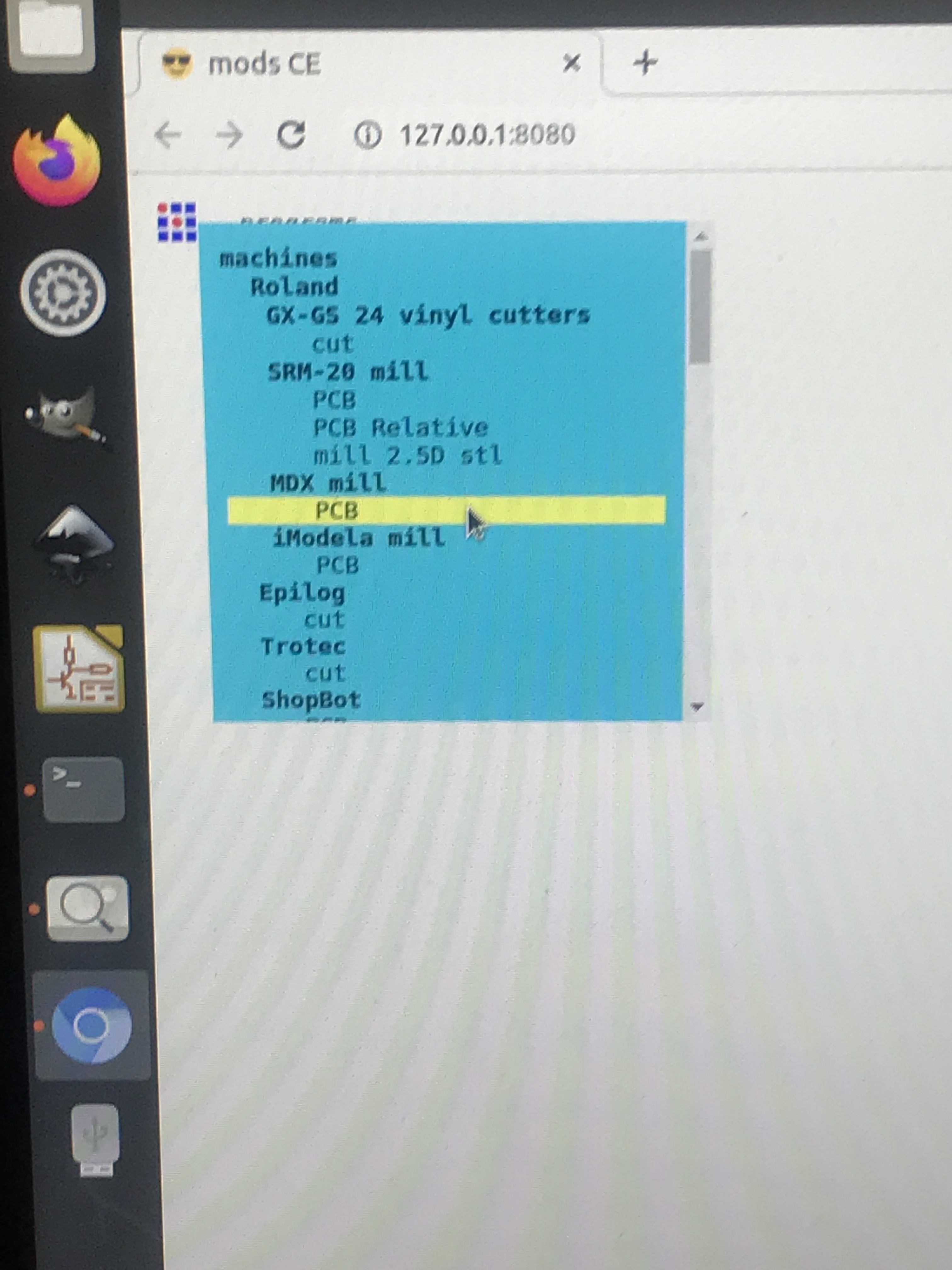
- Right click on the little square on the top and open program then press on PCB under MDX mill
- Open png or svg file, always start with traces
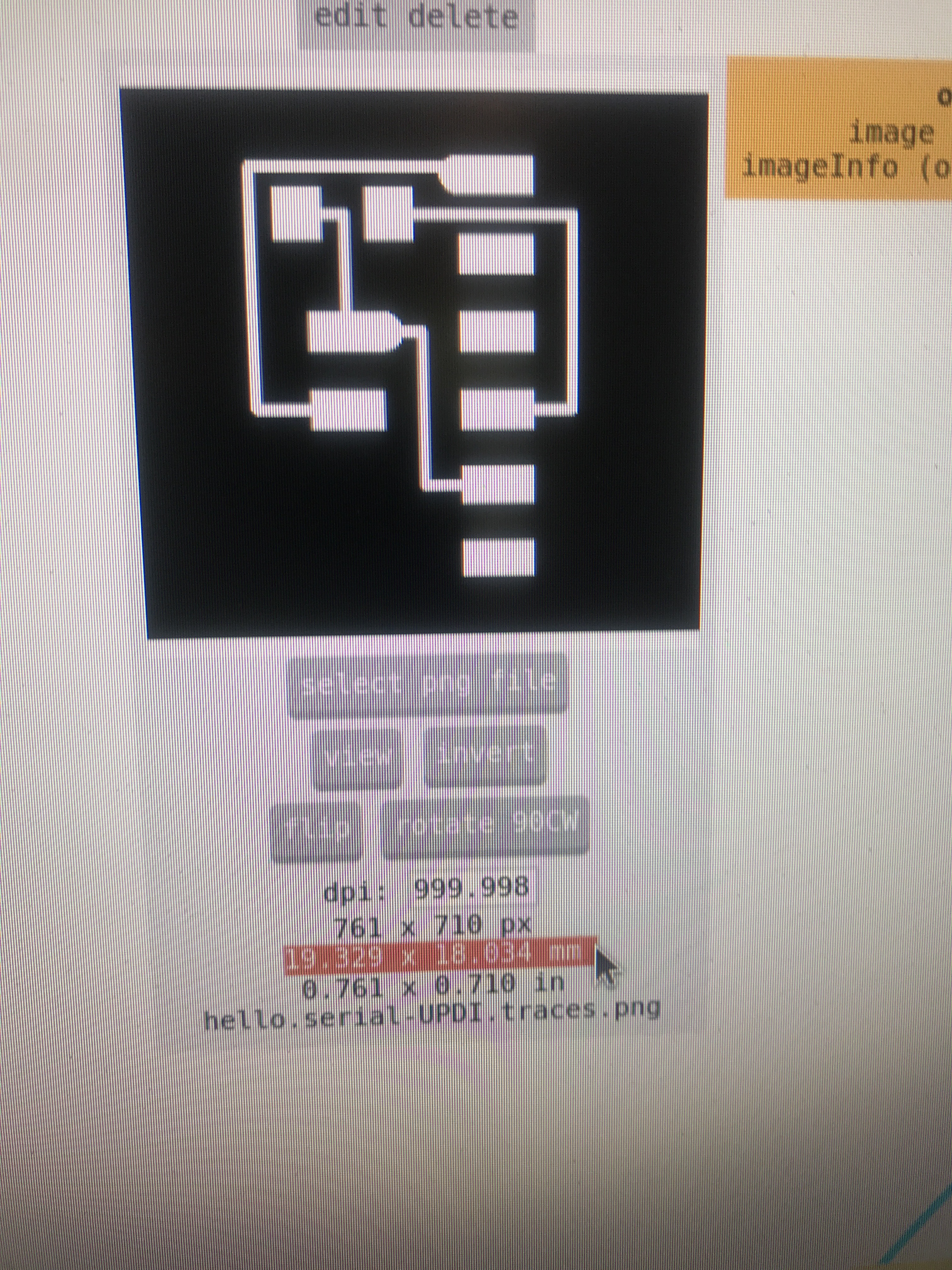 DPI is dot per inch
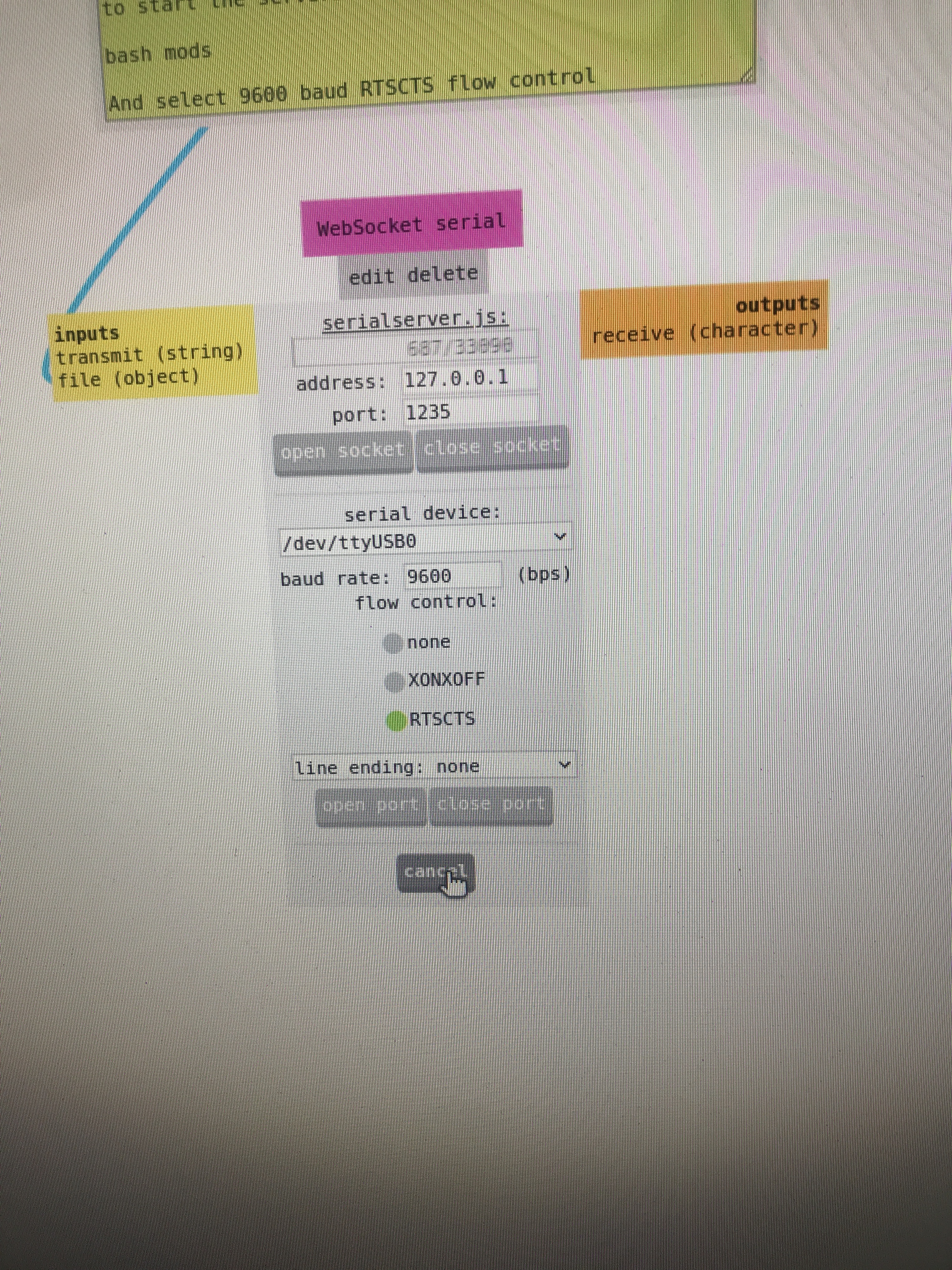
- Close all sockets and boards
- Open web socket serial
- Open socket open port
- Press view (on machine)
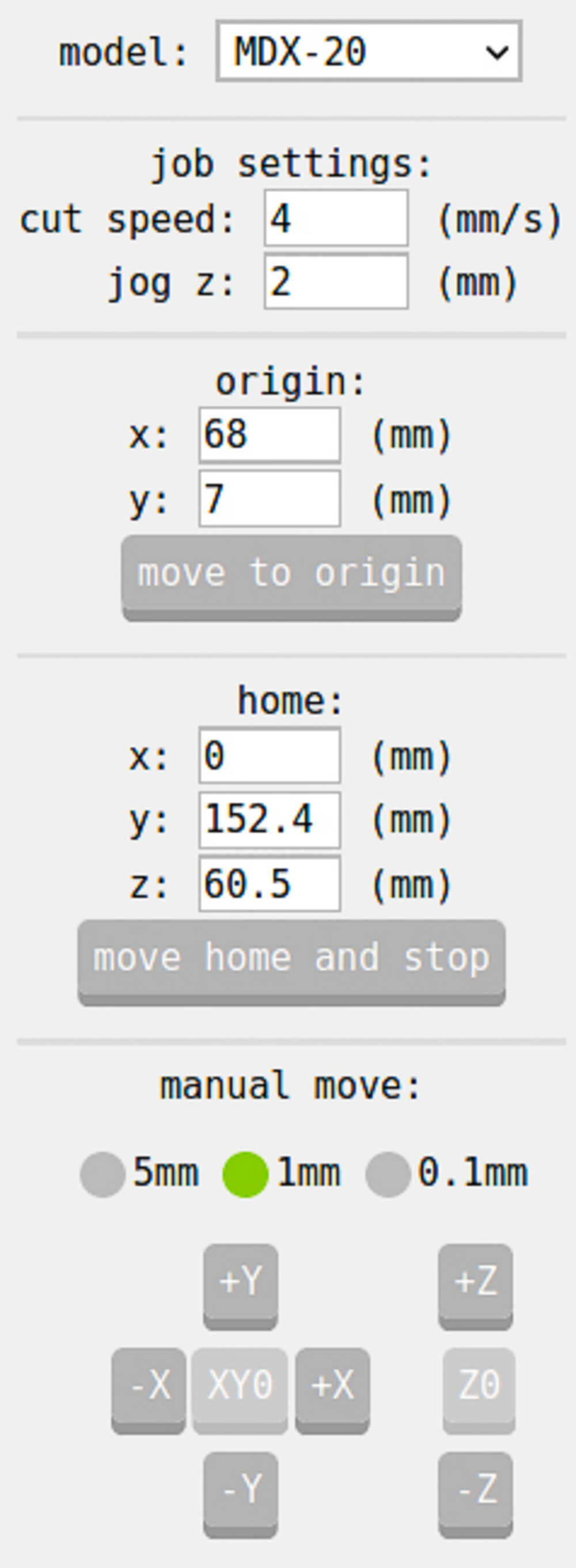
- Set origin by clicking on the up and down arrows branched from tool (on machine)
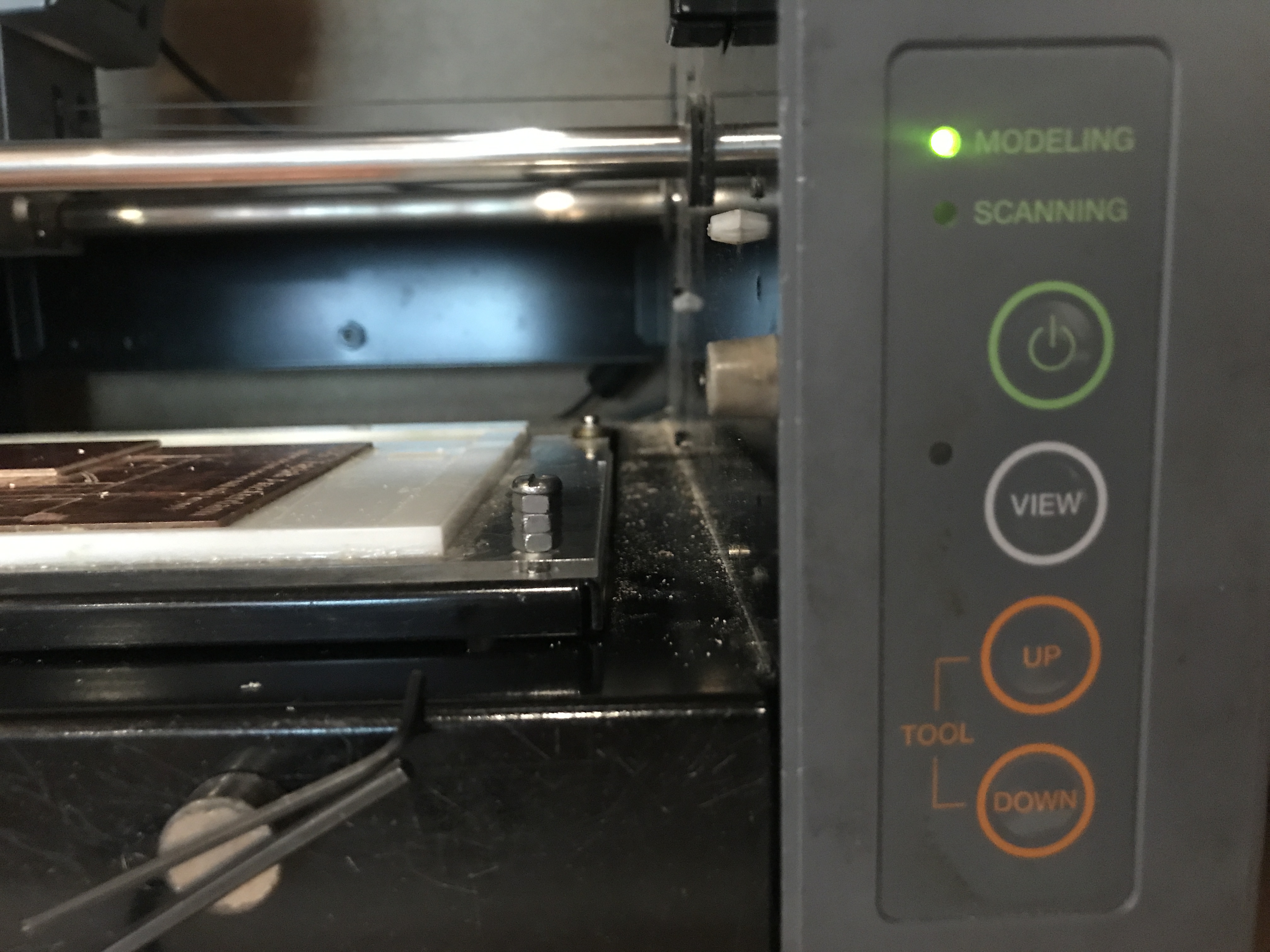 Power on, view & setting origing with the up and down clicks
Replacing Milling bits :
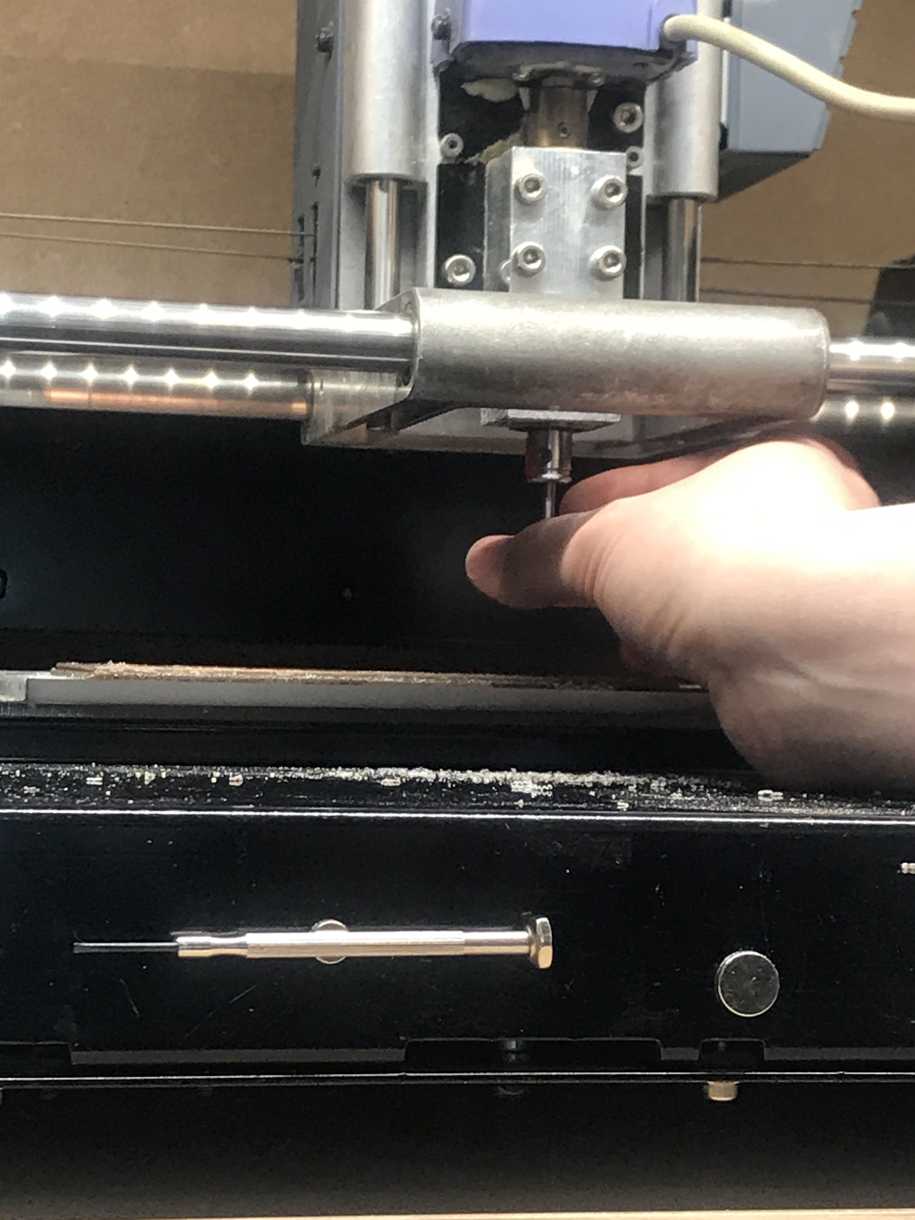 Tip : Put your finger behind it while removing it so it doesn’t fall
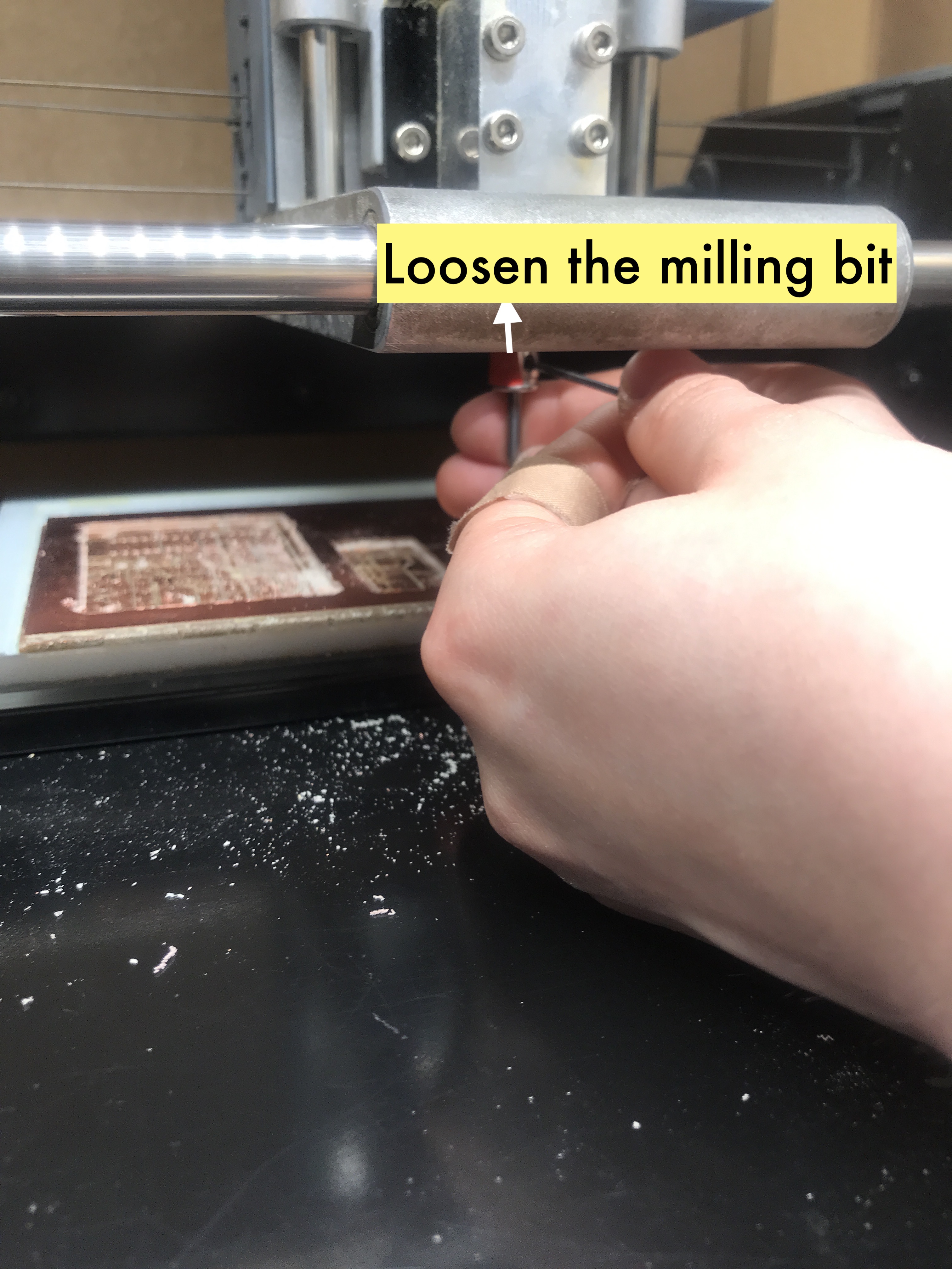 Tip : On the right of the red sticker, you can find the little hole to loosen it up
Tip Be careful not to take out the little circle attached to it.
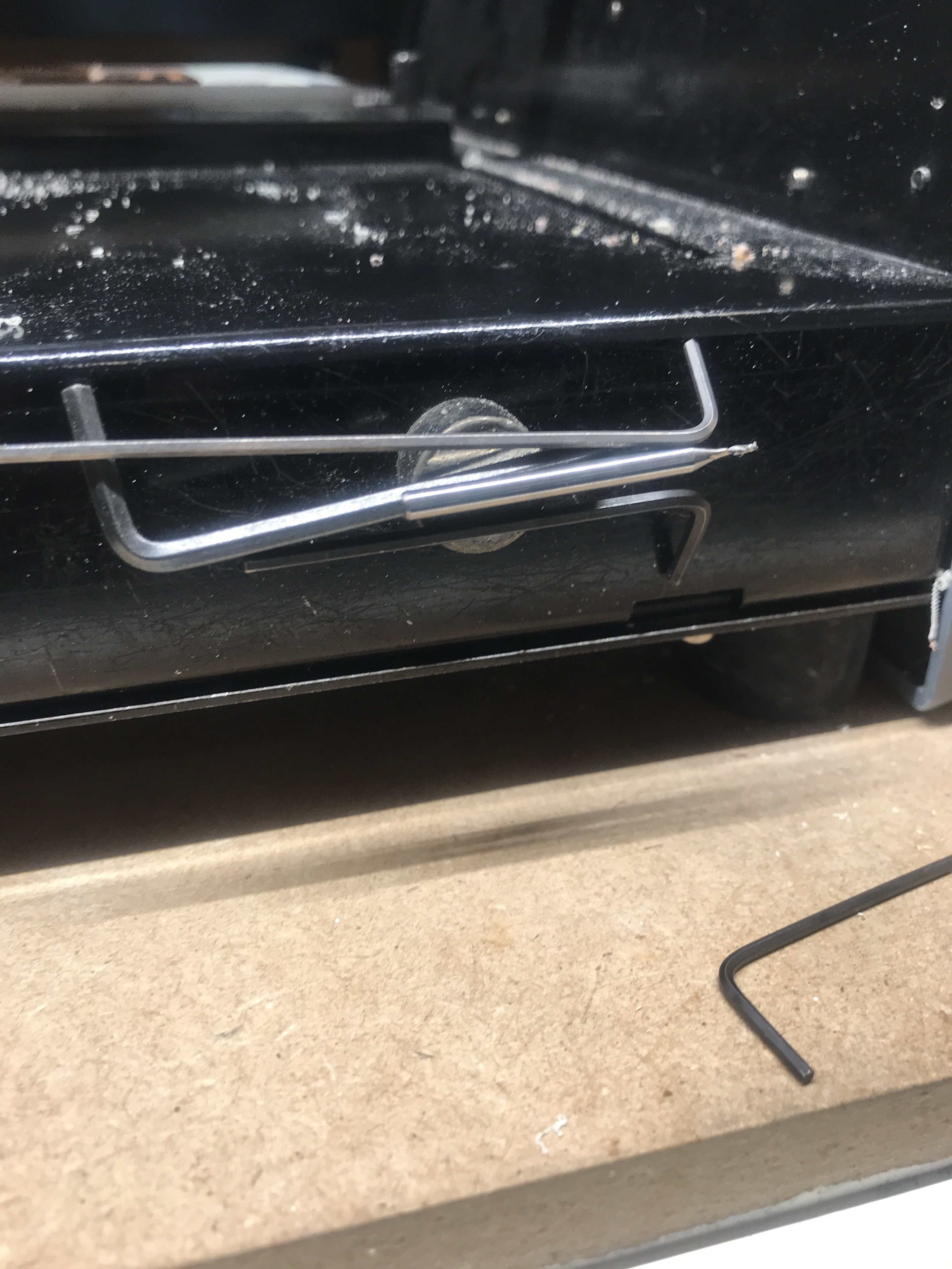 Tip : You can find the pieces used for loosing on the little magnet on the bottom right
- push the milling bit all the way up
 Tip : Tighten it but don’t over do it!
-
Click on the down button all the way until the tip touches the board then go slightly up
-
Level it on this surface and move it around slightly, make sure it’s not all the way up anymore, bring it down so its touching the surface exactly
-
Wiggle it out a bit then tighten it again
-
Then mechanically set level Z
-
Don’t manually move to set an origin because if your origin is set differently on the software, it will go to the manual one instead.
-
If your board is previously used with some empty space on it, measure the empty space to make sure it fits.
-
Take a picture of your origin parameters incase the program crashes.
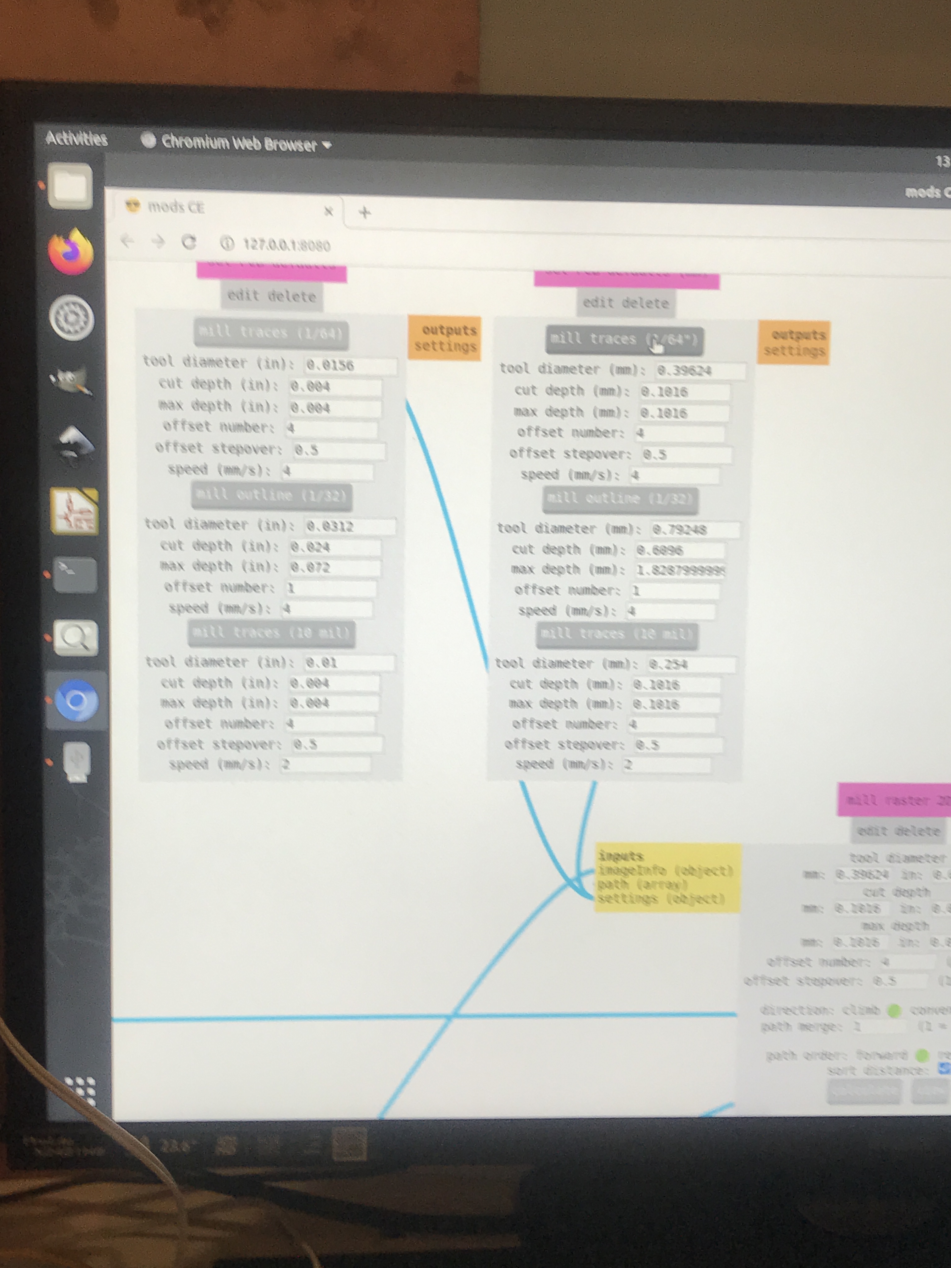
Setting Parameters in mods :
-
Invert selection and see if you need to add an extra 0, sometimes if the file is imported not to scale, then it could be too small, for example assuming that a line is 4 mm instead of 40 mm.
-
In the set PCB default section, press cut depth & max depth to 0.05
-
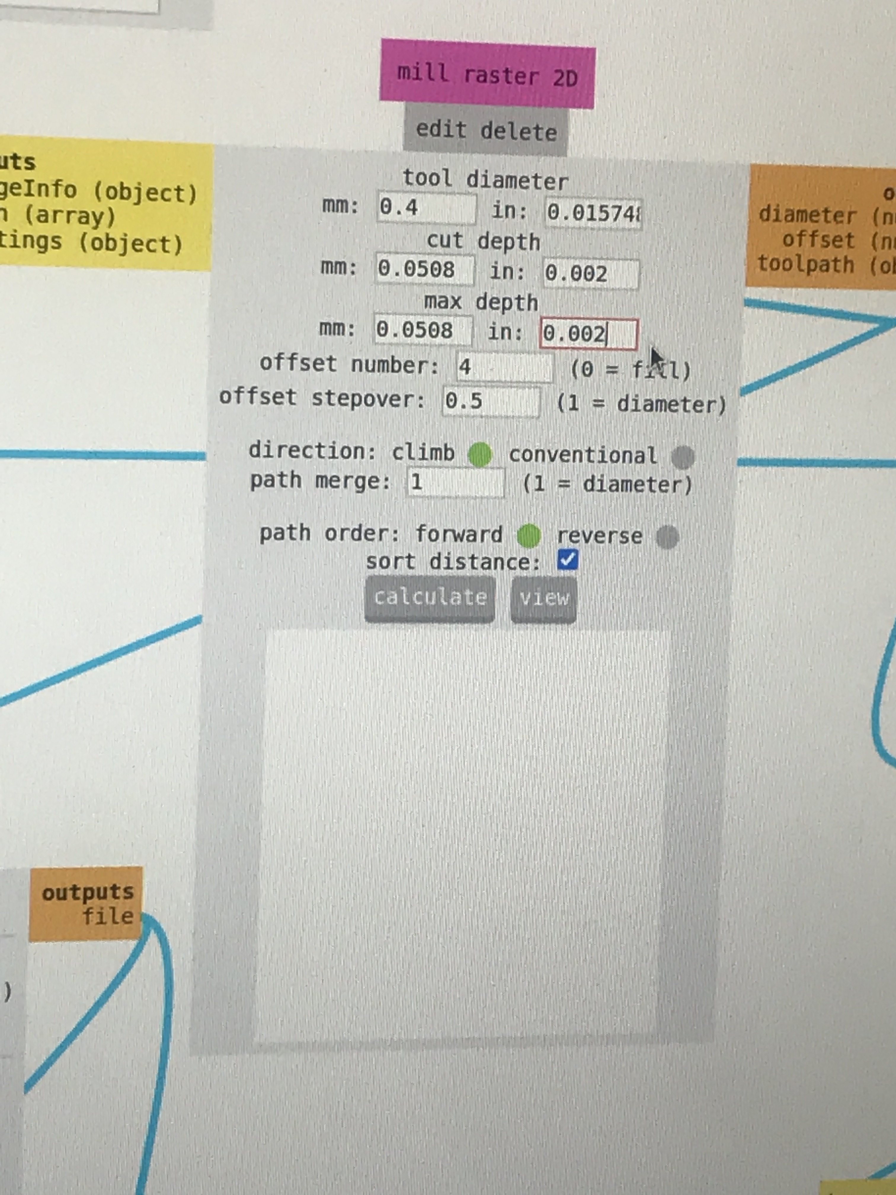
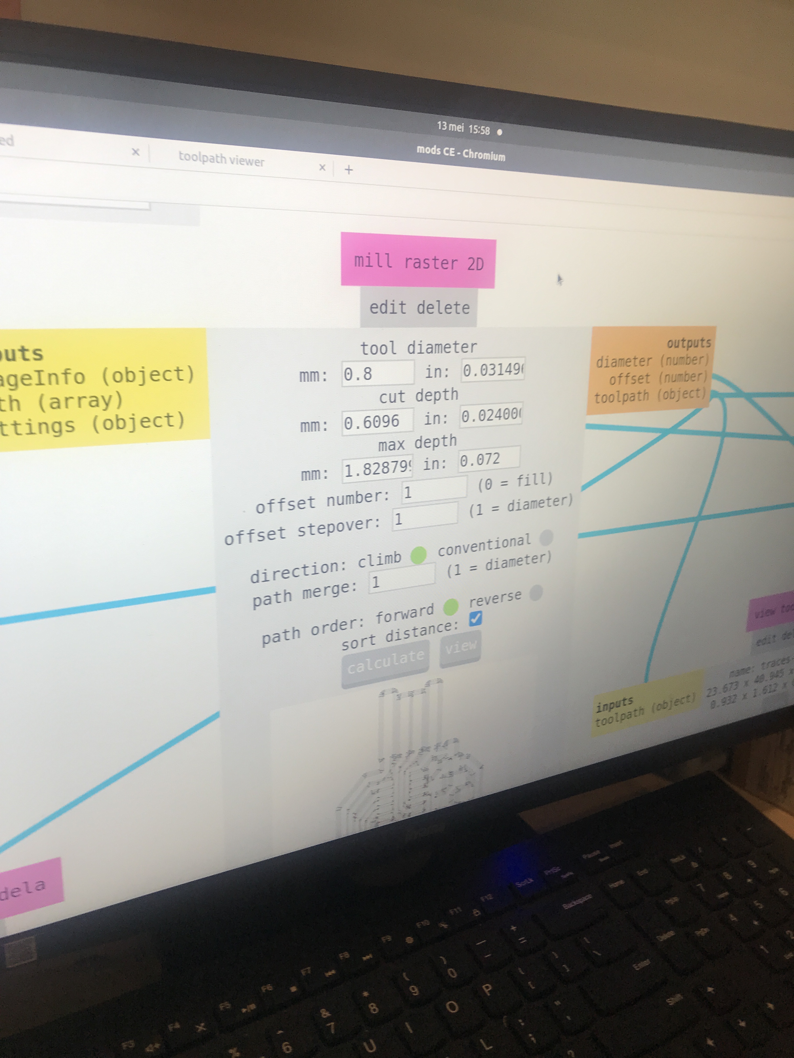
Press Mill traces button first then Mill raster 2D tool diameter
-
Offset number is the amount of lines you are going to mill from the traces, 4 is a nice number for soldering
-
Step over is the same as with the CNC 0.5 for 0.4 not for 0.8
-
For the direction, does not matter which one you choose.
-
Path merge 1
-
Path order, click forward
-
Press calculate
-
Review your file and check, if the preview looks weird then something is wrong Black area is important. Play with threshold to fix it.
*Tip : The black area is the are that will get cut away and the white one is what remains.
-
Press calculate again
-
Send file
- It will start milling away!
We noticed that the depth was not enough so we wanted to change it, we had to pause and reset it.
- Tip : if you press view while it is milling then it will pause.
- Reset it to empty the memory by holding the up and down buttons simultaniously for a while.
- Press view to go to its origin
- Press move to origin
- Play with the cut & max depth of the mill raster
- Send file again, pay close attention to how it is cutting, if the path looks dark then it is going through and it is all good!
- Close it, the light will switch off indicating that it is closed properly and wait for it to be done.
Repeat steps to prepare for outline file
Parameters for Outline
Load the outline file Set the cut speed to 4 mm/s Tinker the setting of the mill outline on the right side because it is metric
- Set Tool diameter to 0.8 (when we tried it, the path did not work so we went for 0.08, again could be a problem with scaling)
- Set Cut depth to 0.6
- Set Max depth to 1.6
- Set offset number to 1 (it’s only going to be one cut out)
- Don’t change anyhing with the offset step over
-
Press Calculate
-
If something doesn’t look right in the preview, play with threashhold and calculate again, we settled on 0.95 and it fixed our problem
- Note: Red lines are travel moves, it should all be black
Repeat steps
- Move it to origin
- Change milling bit
- Press up (Up all the way)
- Put in the 0.8 milling bit & screw it back
- Move it all the way back then a little bit up
- Then tighten it a bit more and while with your finger to make sure that there is no dust under it
- Calculate
- Then press start (load file)
Problems I ran into and how I fixed them :
- Forgot to bring the milling bit down after moving it slightly up, so it wasn’t touching the surface. *The program crashed at some point, putting the origin paramters in somehow did not move to the same spot.
- The scaling problem when it came to the outline, 0.8 did not work but 0.08 worked fine
- Forgot to invert selection
- Sometimes when I tried opening and closing ports and sockets, it still didn’t work so had to close everything and run again through terminal.
Soldering tips and tricks
- Place the soldering iron tip on the location you would like to solder and hold it firmly
- Then melt the solder while still holding the soldering iron tip in place
- If you want to remove some extra solder there is three different ways to help you do that.
Components
There are many different components available at the fablab
To familiarize myself with some concepts in relation to electronics, I turned to the Art of Electronics by Paul Horowitz
Electronic circuits, there are two quantities to keep track of :
- Voltage
- Current
The most useful device to measure voltages & currents is called oscilloscope