Back to basics, for today I will practice some simple exercises such as making an LED blink!
-
A red LED drops about 2 volts while blue drops about 3 volts, for a resistor 15 mA is a good amount. Anything from a 100 to a 1000 ohms is fine.
-
Connect the Resistors in a series with LEDs, not in parellel
-
I tried also to put different LEDs in a series and make them blink simultaneously. I also explored the analog pins (instead of high or low, the numbers are in between 0 & 225)
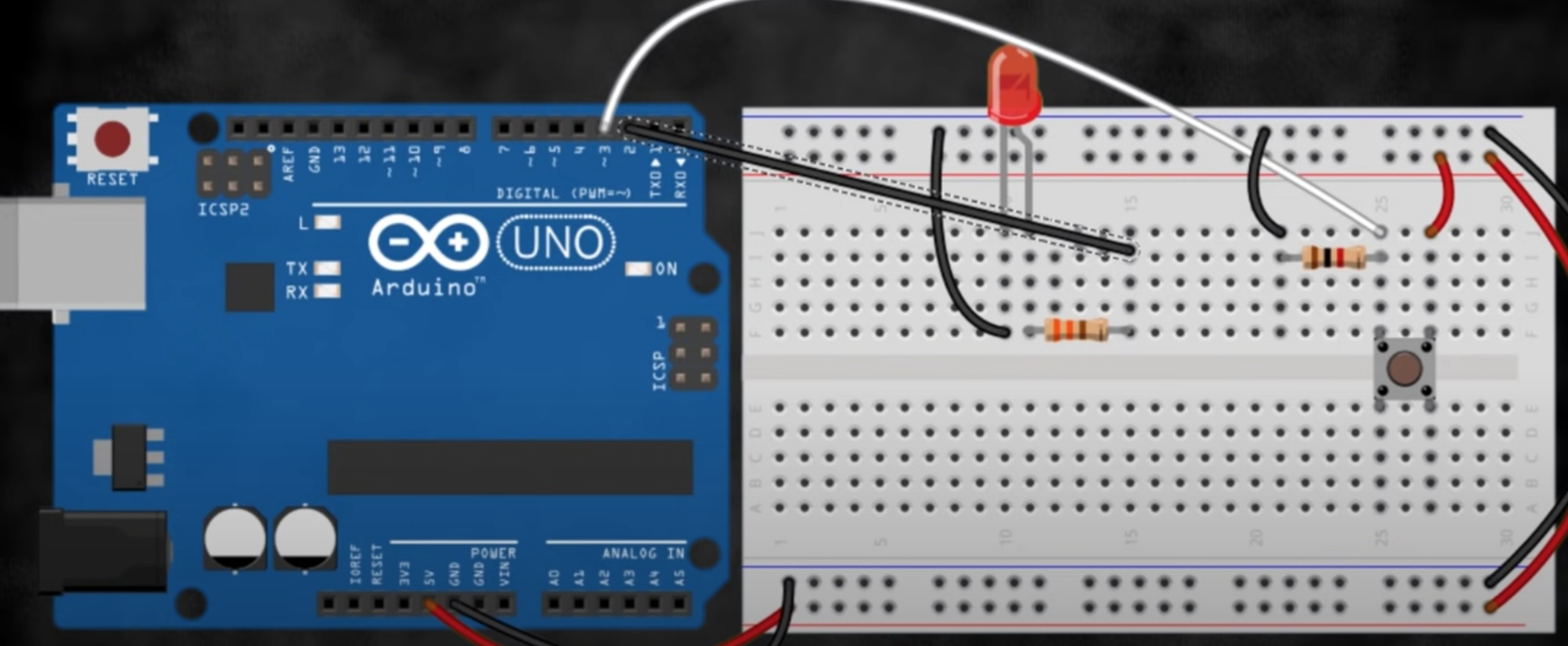
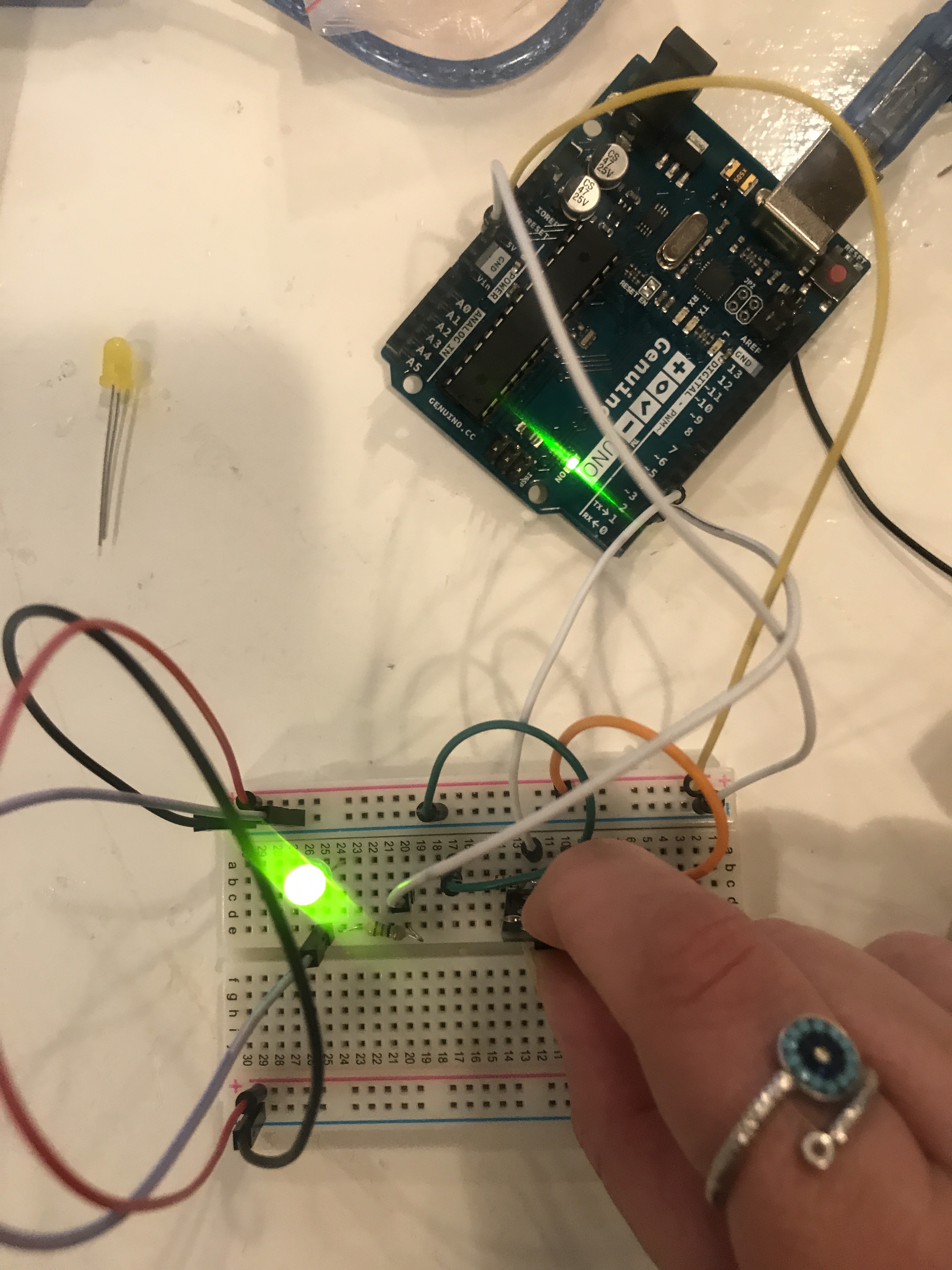
Adding a push button
What is needed :
- An arduino board.
- A bread board.
- LED
- Push Button
- Wires!
- 2 resistors (18)
setup:
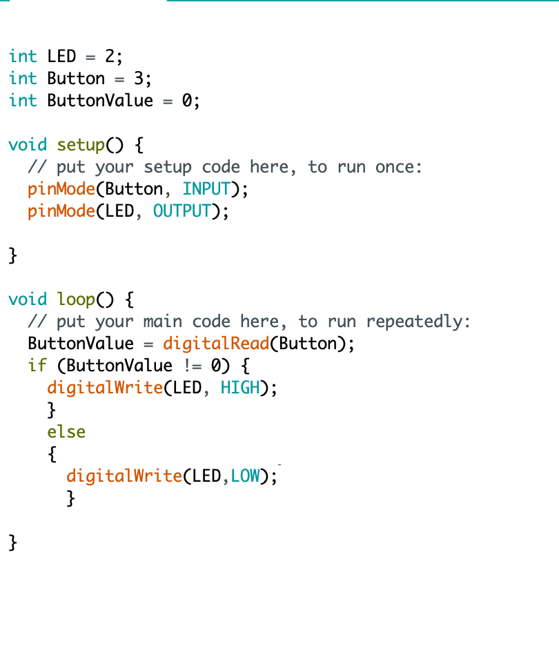
Code:
I then tried the switch button with multiple leds
#### Understanding push buttons & pull up & pull down resistors
-
Depending on whether you place the resistor to the ground or to the 5v, the 5v would be a pull up resistor because the current flowing to open the circuit is going up and with pull down it is going down to the ground. Open reads HIGH or 1 and short reads LOW or 0
-
If we add a digitalRead
#### Potentiometers
Potentiometers are a way to control the amount of resistance voltages moving from 0-5 and the middle one should be connected to an analog pin, the arduino reads a number between 0-1023
The number above the knob is the total number of resistence, for instance the one I am using has a 10k total, but really inside there are two resistors and when switching the knob the amount of resistence changes depending on which one we are turning on or off.
Total resistence (RT) = Resistence1(R1) + Resistence2(R2) Voltage would be the current subtracted from the total resistence (I/RT)
Voltage out which resides between first resistence and second resistence equals the current/R2 so if I = 0.5 mA and the reisstence in r2 equals 0 then Vout = 0
tip : to tell the arduino that a value is not a dicemal yet a fractual number add a dot for instance to read a value (5./1034.) and declare it as a float in the beginning
Potentiameter value goes from 0-1025 while the led value goes from 0-255
- When we read from the potentiameter we use potVal
Reading Data from the Serial Port
First you ask, then you wait then you read.
-
First you start a communication between the arduino and the computer by adding Serial.begin(9600); to void setup
-
before void setup you can declare what the end user will read to insert their input for example String msg = (“type your msg here”); as a variable
- In void loop you can say Serial.println(msg);
-
To read the value, you can put it in a while loop while (Serial.available()==0) {} basically telling it if the value is 0 don’t do anything, and once the user adds a value then leave the loop here you can add Serial.parseint() which looks for the next valid integer in the incoming serial.
-
Serial.readString(); reads the value the user has entered then we can say Serial.print(the variable assigned for example msg); Serial.println(variable); means print this on the next line.
- I tried another exercise, where the user can enter which led they want to switch on based on color, and based on the user’s input the assigned led can switch on.
For this exercise, I connected 3 leds to appropriate resistors, ground and one digital pin. then using the serial read function, basically told it if it reads blue as in if the user types blue inside the serial monitor, then switch pinBlue on, pinRed off, pinYellow off delay(keeping in mind the variable assigned) and off then repeat the same for the other twp.
RGB Sensors
- Cool fact you can get a variety of colors by playing around with the RGB values.
Temperature sensor & blinking LEDs
Dallas 18B20 can read temp from - 55 to 125 and has a resolution of 9-12 bit and has a 64 bit addressing
The sensor has 3 legs, far left is GND, second one is data and last is VCC
- Note that the rounded part is facing away from the arduino, for more info refer back to the datasheet
for this exercise, I followed one of the projects mentioned in the Arduino Projects Book that connects the temp with 3 blinking leds.
Because I’m using a different sensor than the one mentioned in the book, I faced some problems,
There are two types of transistors :
-
Bipolar
-
Field Effect
There are two functions for transistors :
-
Switch circuits on and off
-
Amplify signals
The left leg of the transistor functions as an emitor while the right leg functions as a collector and the symbol for the emitor side is marked with an arrow. The current always flows from the collector to the emitor and therefore the emitor should always be connected to ground
Understanding Pulse Width Modulation (PWM), it rapidly turns the output high and low over a fixed period of time, it acts as if you are changing the voltage.
- The percentage of time a pin is HIGH in a period is called duty cycle. When the pin is HIGH for half of the period and LOW for the other half, the duty cycle is 50%
Digital pins 3,5,6,9,10 & 11 are set aside for PWM and can be identified with ~ which have an analog value between 0 and 255 which corresponds with 0 - 5 volts so instead of saying HIGH or LOW we can say 255 which corresponds with HIGH and 0 which corresponds with LOW and the values in between will determin how bright the led will be.
8 bits of resolution
Photoresistor
A Photoresistor is a resistor which is made of semi-conductor material, it changes their resistance depending on the amount of light that hits them, also known as photocells or light-dependent resistors.
Servo
First to include the library install it! then add #include name of library.h
I tried different exercises, in one of them I attached a photoresistor to an analog pin and used it as input to read how much light is hitting the resistor and depending on the amount to move the servo left or right indicating brightness or darkness. The angle of movement was calculated following the tutorial.
Some new terminology with servo, you can say servo.attach and indicate which pin is conencted to it. for instance you could first name servo myServo then say inside a void setup myServo.attach(9) indicating that it attached to pin number 9.
myServo.write
The second exercise was
Active Buzzers to add sound
There are two types of buzzers :
- Passive, you have to apply an AC signal - move from a digital high to a digital low. You can get different tones out of it as well as tunes.
- Active is easier to use,
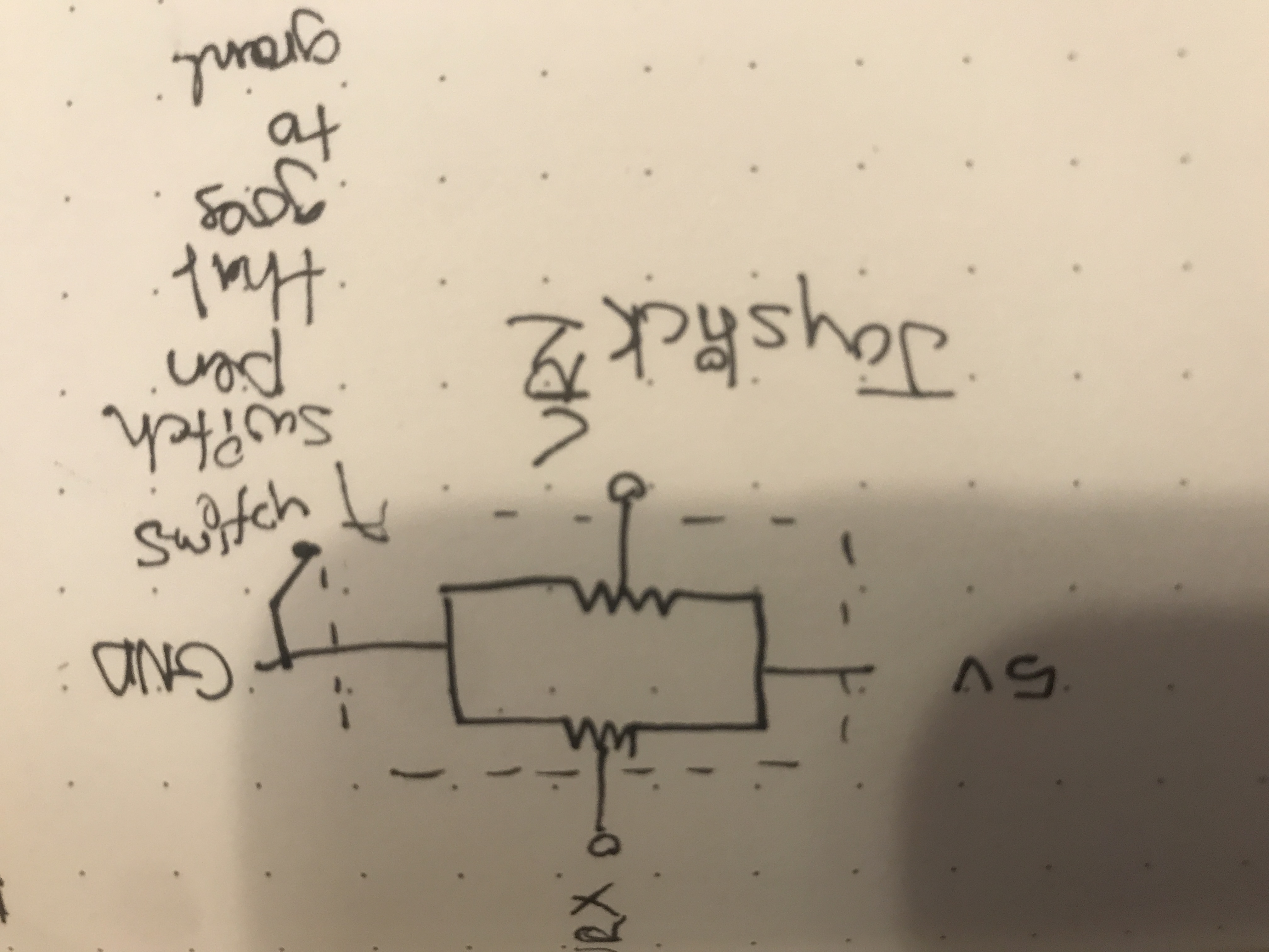
Joystick
- Ribbon Cable is going to be needed
- the joystick sensor circuit is drawn this way
Joystick to control a servo!
Stepper motor
Hardware part:
-
One important component was missing(the power supply), so I watched the tutorial without following along
-
First step was to connect the power supply to the bread board,where the + goes into + and 1 goes into -
-
Second step was to connect the ground of the power supply to the ground of the arduino
-
Third step was connecting the IN1 - IN 4 on the stepper motor driver to pins 8-11 on the arduino board.
-
Forth step is to connect the little - + pins on the stepper motor driver to ground and power, very important that its not directly to the arduino yet powered by the power supply, alliged with the position of step one.
-
Fifth step is to plug in the 9v battery to power supply
-
Add a push button to the bread board Same for the DC Motor!
Software
- load library

some terminology associated with the stepper :
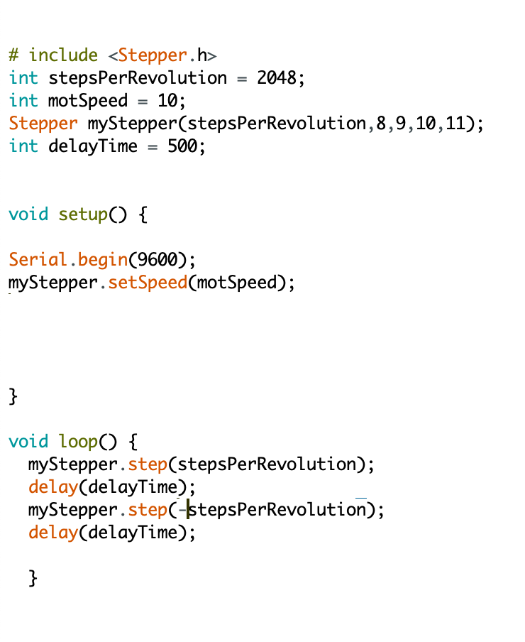
- Steps per revolution can be found on the datasheet of the stepper, for instance the one I tried to use has a 2048 steps, this number is important to define how many steps exist in one lap or circle. you can define steps per revolution as an int before the start setup and assign the number in the datasheet to it.
- There is also a command called Stepper from the stepper librar, you can define the stepper by typing Stepper (give it a name) such as myStepper (tell it how many steps for this motor to complete a cycle/ a revolution) and since we already defined that as stepsPerRevolution, we can include the name of the variable. then afterwards define the pins that the stepper driver is connected to, 8-11. so it would look something like that : Stepper myStepper (stepsPerRevolution,8,9,10,11); In the void setup we can define the speed of the motor, myStepper.setSpeed also part of the library then (name of variable) which should be defined as an int, we give it a variable to indicate the speed of the motor which is defined before void setup i.e. int motSpeed
so the line of code would be : myStepper.setSpeed(motSpeed); These stepper motors can’t run too fast, so giving it a 10 rpm
-
In the void loop, we can tell it to turn one cycle clock wise then turn one cycle counter clockwise :
- myStepper.step(stepsPerRevolution);
- then give it a delay :
- delay(delayTime), also a variable indicated before void setup i.e. int delayTime = 200;
- myStepper.step(-stepsPerRevolution);
- delay(delayTime);
Adding a push button to the same setup
The interesting part here is to use the push button as an inputPin then write on it with a digitalWrite and give it a HIGH.
Tilt switches
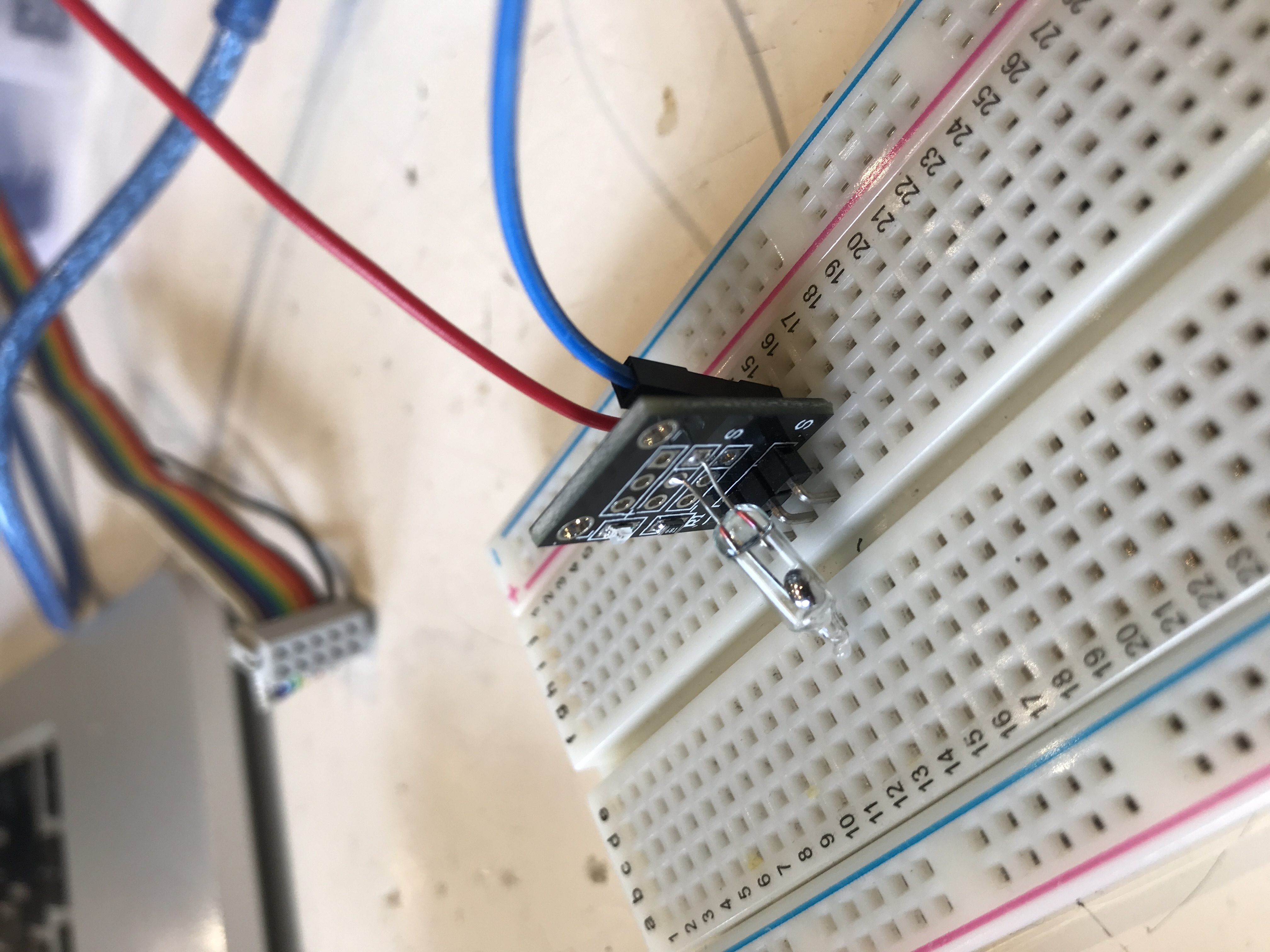
As the name implies, it switches value when you tilt it! It’s pretty fun and simple!
The following example sends an order to light up a green led if it is tilted downward and light up a red one if it is tilted upwards
Understanding Hexadecimal Numbers & Why they are important
-
Computer are really good at one thing, turning on and off tiny switches over and over again.
-
You take on data (music, visuals, whatever you want) and turn it into numbers, 0s & 1s. For example, I can represent any color with a bunch of zeros and ones i.e. 11111111 represents green. Through the serial monitor you can translate the numbers to hexadecimal numbers or binary. With hexadecimal numbers after reaching 9 (4 binary digits) we switch to A which is equal to 10 in decimal numbers and 1010 in binary. With hexadecimal, it is easier to keep track of commands than binary. You can also tell the arduino to read in decemal. Serial.println(byte,DEC);